A few years ago I wrote a post about using a logic analyser to read an EEPROM on boot up. This was a bit too simple and passive for my liking, but, it worked and I got the data I wanted.
Now I’m going to expand on how to do this by reading directly from the chip the same way the CPU does.
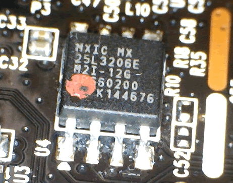
One of the common “attacks” on IoT devices is to read the firmware or data directly off its storage. Commonly this data is stored on a single EEPROM, which generally looks something like this:

The above chip is a Macronix MX25L3206E NOR FLASH chip which is being used to provide storage for a cheap D-Link camera, the same one that was ripped apart by my colleague Jamie a while back.
I just thought I’d do a simple post about the ways to read this and some of the common pitfalls.
Reading a simple flash chip is generally quite simple, as to minimise complexity on the circuit board they commonly use I2C or SPI as basic protocols, which can easily be used to read its contents.
Of course, this sometimes only applies if the chip is removed from the board. Depending on the board’s design a simple attempt to power the chip up whilst the board is off, or to talk to the chip whilst the board is active may fail. This is one of the reasons I chose to use this device to do the read, as I know the read can be performed without powering up the device.
The basics
According to the datasheet (which you can find by searching for the part number with your favourite search engine), this chip uses SPI for communication.
SPI (Serial Peripheral Interface) is a simple serial communication protocol, that uses four wires for data transfer and can work across multiple devices (i.e. it forms a bus):
| Wire | Name | Use |
| CS | Chip Select | Used to specify whether the chip is selected, more commonly known as slave select – SS – or Enable |
| SI | Serial Data Input | Used for data input to the chip, more commonly known as MOSI – Master Out, Slave In |
| SO | Serial Data Output | Used for data output from the chip, more commonly known as MISO – Master In, Slave Out |
| SCLK | Clock | Clock line, used to set the timing of any communication |
Transferring data over SPI requires sending of binary commands with parameters and receiving the responses. The easiest way to visualise this is to, well, visualise it.
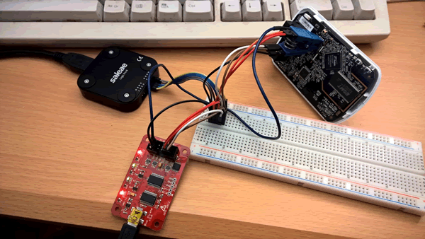
I set up a logic analyser inline whilst I read the chip to try and demo it. This is a bit wire intensive, and stole a lot of USB power from my laptop (and yes, I now see how much I need to clean my keyboard):
This allows us to capture the traffic as we read it, which looks something like this:

Here we can see three bursts of data, we can see CS (called ENABLE here) forced low during the burst, a spike at the start from MOSI (SI) and activity on MISO (SO) and CLOCK (SCLK).
Zooming in on the first burst allows us to see the byte patterns:
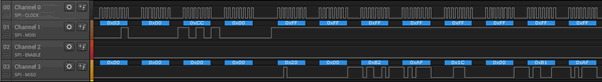
From here the clock is immediately obvious – it runs a regular pattern which coincides to data transfer. The burst starts with a code on MOSI of 0x03 0x00 0xcc 0x00 and then proceeds with data being returned on SO.
Looking at the datasheet we can see that 0x03 is the instruction for READ:
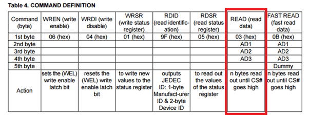
So we can translate the above instruction as READ 0x00CC00 and it will return bytes from that address until CS aka ENABLE (you get used to pins being called different things by different people, honest) goes high.
In theory, we could now write a program to do this for us. Fortunately people have already thought of this and we have both software tools (in this case flashrom) and hardware (in this case the Bus Pirate) to do the hard work for us.
All that is left is to wire it up and connect it together.
I’m using a clip to make my life easier – although you can just use hooks to connect to the right leg. I’ve had a load of cheap import clips which never really worked, after a lot of wasted time I ended up throwing them away and getting some decent Pomona ones which are easy to wire and make a solid connection to the chip legs.
The wiring to the chip can be seen in the data sheet
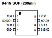
This makes it easy to wire to the same pins on the Bus Pirate. Once we’ve done this we can read it in one command:
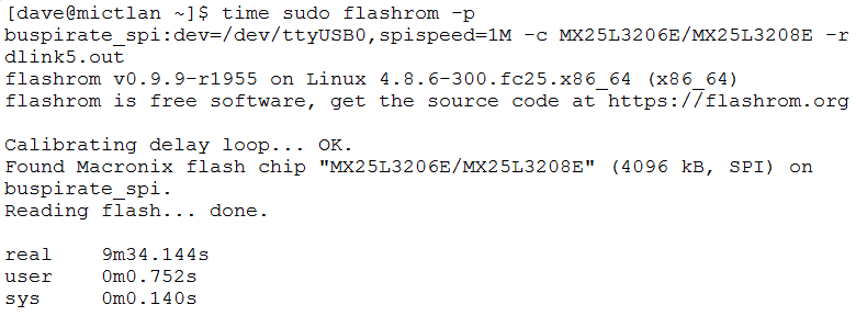
I timed the above transfer so you can see how long it takes: 4 MB in 9 minutes 34 seconds, which works at about 7 kB/s. This isn’t very fast.
Can we improve it?
Yes we can, we have a couple of options. The first is to use a piece of hardware called The Shikra which is designed to be a slightly faster and more stable tool than the Bus Pirate. There are a couple of problems with this:
- It can only be bought from the US
- It does not provide power to the chip, so I’d have to rig this up separately. This would require me to clear some space on my desk. That may take a while.
There’s also Opale security’s Hardsploit.
One of these days I may write an article to demonstrate these two, but for now I’m going for speed, so I want to be able to access the SPI bus directly, which means I need to use a small computer.
One of my colleagues swears by the BeagleBone Black, but I don’t have one of those to hand. I wanted to try with my PocketCHIP as it would’ve been nice to have an all-in-one solution, but this would have required a kernel recompilation.
So, it’s time to pull the Raspberry Pi 3, that I’ve bought and never used, out of storage. One quick install of Raspbian on it and some faffing with dependency hell to get flashrom to compile and I can try a direct read from the SPI bus.
This will have to be a photo as I needed to reuse my keyboard, mouse and keyboard for the Pi:
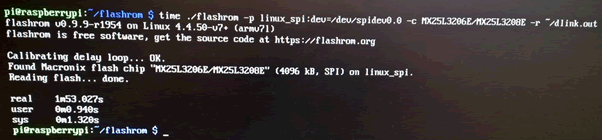
As we can see, this took 1m 53s, or about 36.3 kB/s. This shows what accessing the bus directly does for the speed.