Here at Pen Test Partners we love hardware and also love a good CTF. So here’s how I figured out my way through the hardware CTF that PTP set as a pre-requisite for some interviews. I’m pretty new to hardware, so learned quite a bit along the way.
We have now moved on to a new ‘interview’ CTF so, instead of using it as a testing tool, we have repurposed it as a teaching tool.
This blog will walk through my thought process and each step I took to try and obtain a root shell.
TL;DR:
A walk-through of a home-brew hardware CTF.
Connecting to serial to find it disabled, almost bricking the device via the uboot console and dumping the firmware from an SPI flash chip.
Looking through the file system to obtain a root hash, which was cracked using the johntheripper default wordlist (but not rockyou!) Also finding the Wi-Fi credentials deep within the file system.
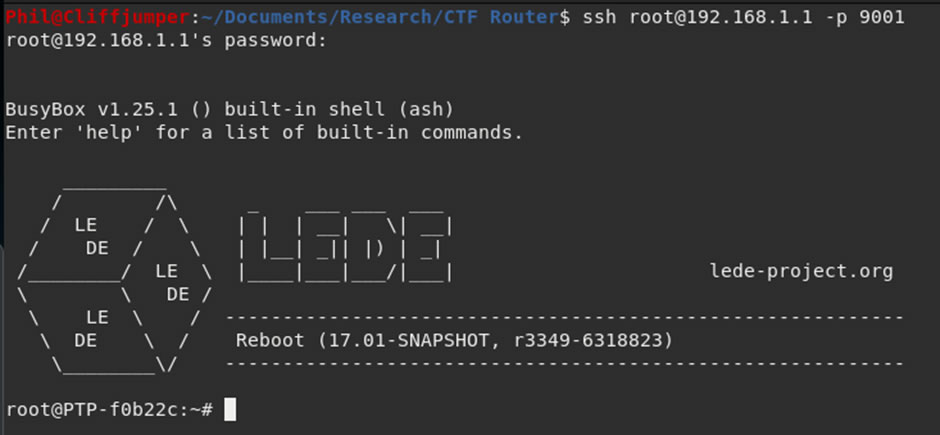
Accessing the Wi-Fi and the web interface allowing bypassing of firewall rules to SSH into the device to obtain a root shell.
There’s also a walk-through video to accompany this post:
The Device
First up is to look at the device, in this case it is a 300M Smart Router:
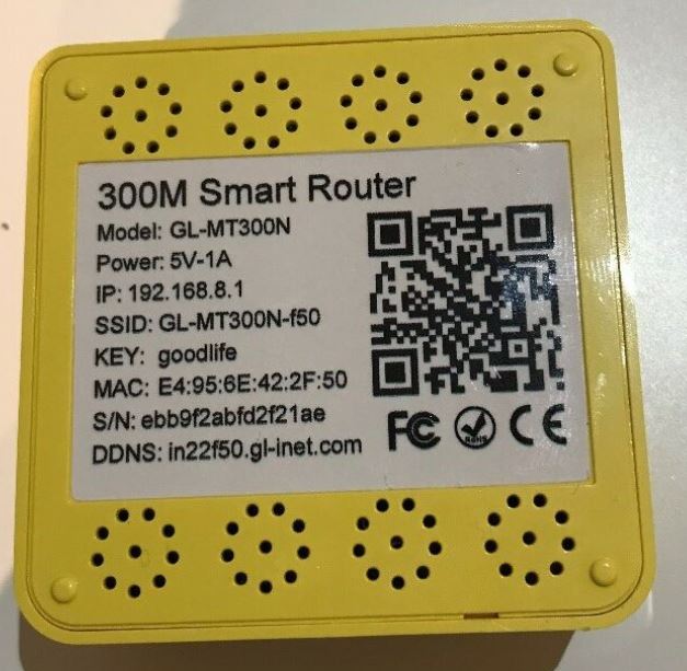
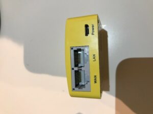
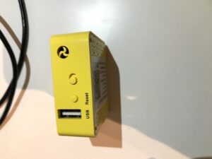
The device has a USB port, 2 ethernet ports (LAN & WAN) and a power port. There is also a reset button and a mode switch.
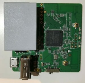
Taking the bottom off the device, we get access to the board.
Front
Back
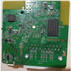
Immediately there are some interesting looking components. There looks to be a system on a chip (SoC), SPI flash and some SD RAM. There is also a serial port and what looks like JTAG and UART.
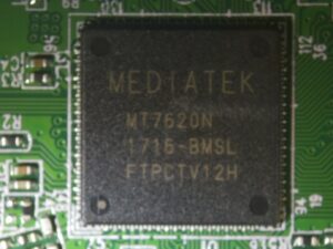
Chipsets
The MediaTek MT7620N is a self-described “router on a chip” and the datasheet shows it has a CPU therefore includes everything needed to run.
The block diagram shows all the functions that the chip has:
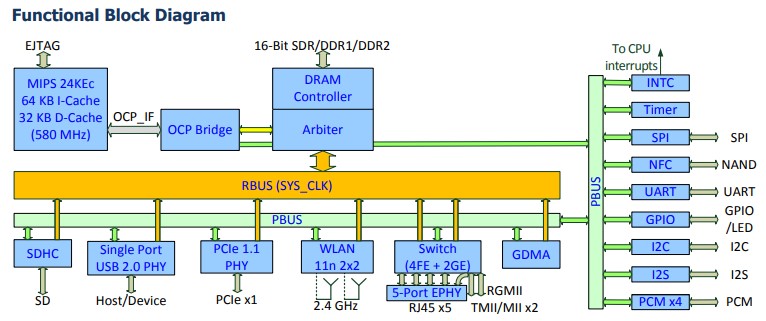
It can be seen on the right, that there is SPI, NAND and I2C. All of which are used to transfer data and are part of the attack surface. It can also be seen that the chip has UART which is a serial console. UART is often used for debugging and might still be enabled, allowing access to the box whilst it’s running.
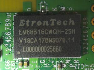
The other chip on the board is the EtronTech SDRAM chip. This is the RAM so will be used whilst the device is running.
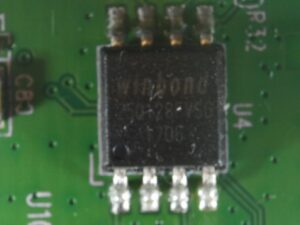
There is also a Winbond SPI flash chip on the board, this usually contains the file systems and any config settings. Looking around the board there is no other storage devices, so this must be where these are being stored.
As the device has both LAN Ethernet and Wi-Fi, before going any further I’ll try to connect to them both and see if I get any access to the device.
Connecting
Wired
First up is to try the wired network, the guide for the device says a web interface should be available on 192.168.1.1 if I have an IP in the same range.
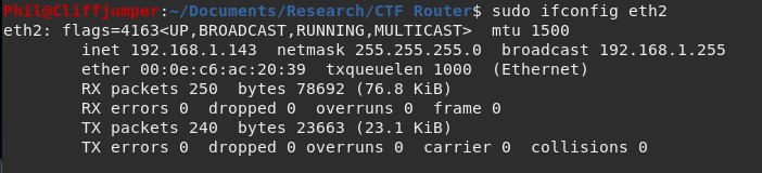
Connecting into the LAN port I discover the device is running a DHCP server which provides an IP address.
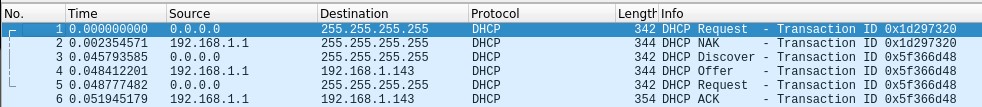
A Wireshark capture shows the DHCP handshake
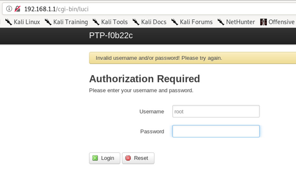
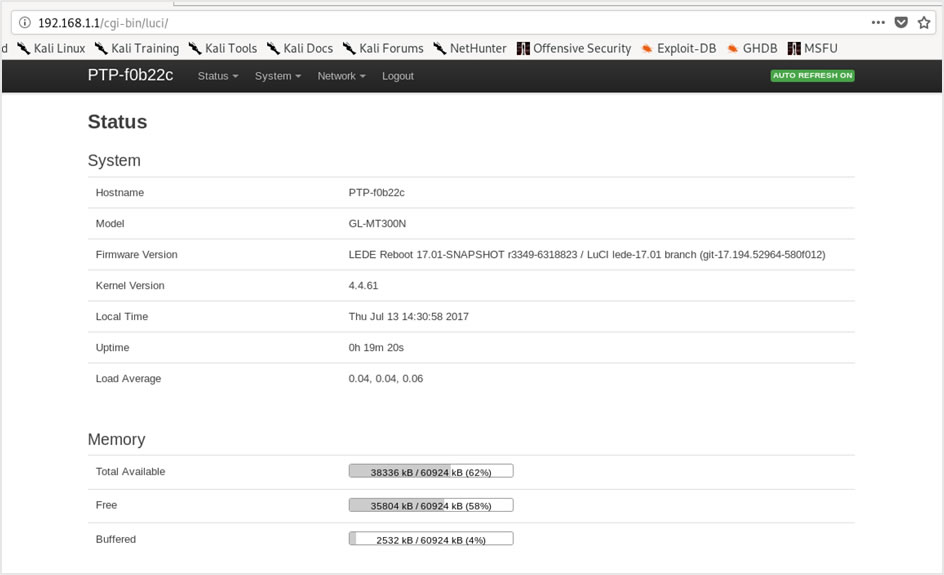
As I’m on the network, it might be possible to go to the default web application running on 192.168.1.1.
The application loads however asks for root credentials, which at this point I do not have.
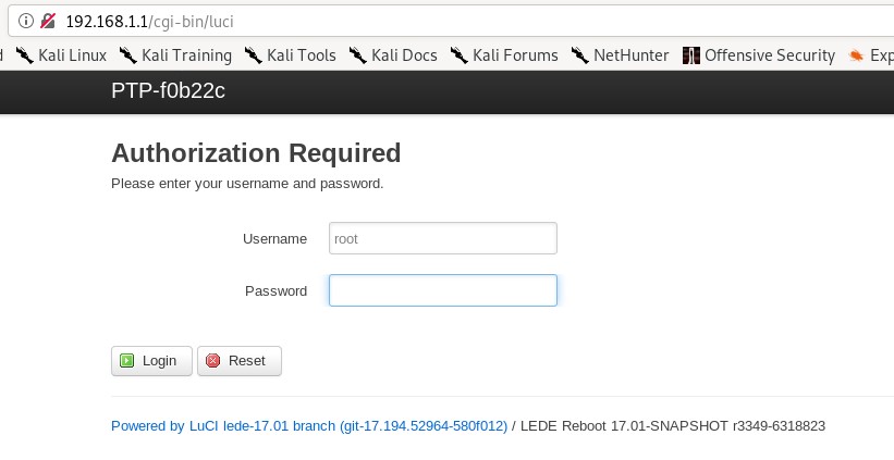
A brute force attack could be attempted, however, it’s unlikely to be the route through this CTF.
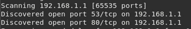
While connected to the device, a full nmap port scan was run to see if there are any other services running that could be of help.
The full scan revealed two ports open:
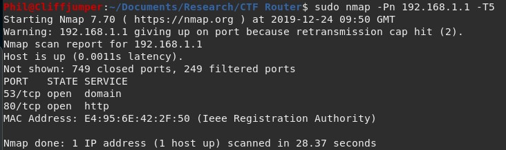
The only one of interest is the web application on port 80. I was hoping port 22 (SSH) or 23 (telnet) would be open for an easy way to connect into the device.
Wireless
Even though I got the login prompt through the wire, it seems sensible to look for any clues in the wireless.
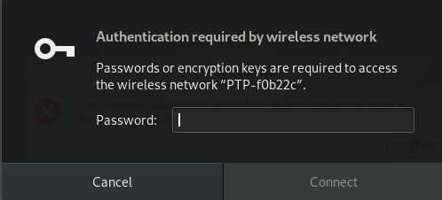
The wireless network can be seen:
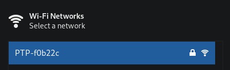
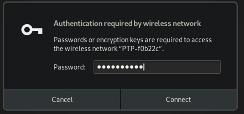
However, it is password protected and authentication is requested straight away.
Looking at the device, learning what it does and how to use it are critical within a hardware test, as it’s very difficult to test the hardware and threat models without understanding the device.
Serial Connection
As limited information was learnt from connecting to the device directly, I connected via the serial console to see if there is an open connection available there, which might provide an unrestricted shell.
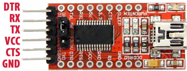
Connecting up to the serial port is fairly straightforward. There are 3 wires, Ground, RX and TX. Also needed is a serial to USB converter, such as the FTDI232 which is what I used.
The converter has 6 pins on it, the pinout is available online:
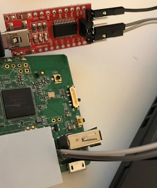
The router has three pins hidden between the USB housing and the ethernet ports that are labelled GND, RX and TX:

Before connecting up it up to the pins, I power off the device.
Connecting up the ground, RX and TX to their opposite counterparts on the serial to USB converter:
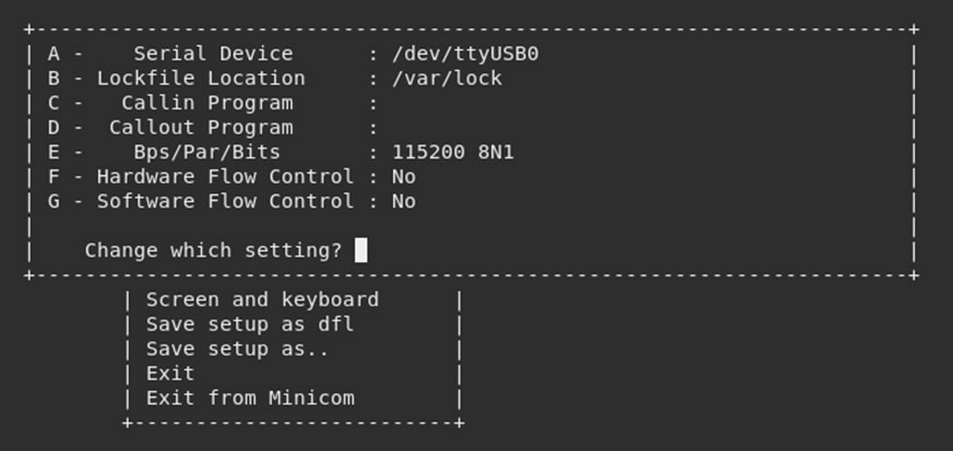
I used minicom to interact with the serial console. This does however need a little bit of setup:
sudo minicom -s
This brings up the minicom settings which are:
- Serial Device – the location of the USB port on my Linux machine
- BPS – baud rate, the rate in which information is transferred
- Par – the number of parity bits and the interpretation of this bit
- Bits – number of stop bits
- Hardware flow control – Hardware controlling the rate of information flow
- Software flow control – Software controlling the rate of information flow
Finding out the location of the device is relatively easy on Linux, looking for USB in the /dev/ directory will list any attached devices.

After connecting the device, it appeared as ttyUSB0.
Calculating the baud rate (Bps) is more difficult and can be calculated using a logic analyser, however, the default baud rate is 115200 and it’s always worth trying before spending a long time trying to find out the information.
There are three options for parity bit, “n” for no parity, “e” for even parity and “o” for odd parity. On this device there isn’t a parity bit, so that can be set a “n”.
For stop bits, there are two options, either 1 or 2 bits. It is recommended that a single stop bit is used.
The device doesn’t have any flow control, so both hardware and software can be set to no, once minicom is configured with the above, it looks like this:
Once configured, I re-opened minicom with the new settings and powered the device.
Almost immediately the device start booting and an output is provided via the serial interface:
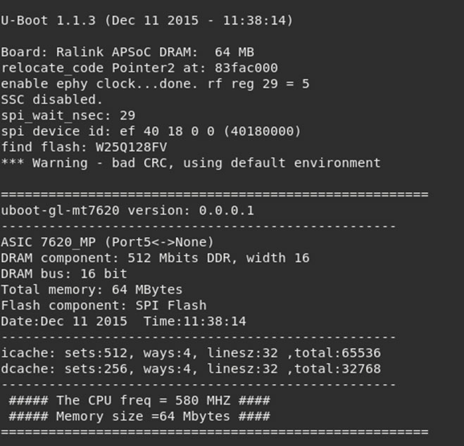
Reading through the data I can identify some components:

Also learning that the device uses both squashfs and jffs filesystems.

However, on the second to last line is the critical information:

The serial console has been disabled. This is good security practice as it stops a simple attack vector which could ultimately provide an authenticated shell.
However, it might be possible to stop the loading at the u-boot section, which could provide additional information. When the device boots there is an option:
“Hit SPACE to stop autoboot”
Hitting space from when the device starts up, it’s possible to drop into a uboot shell:
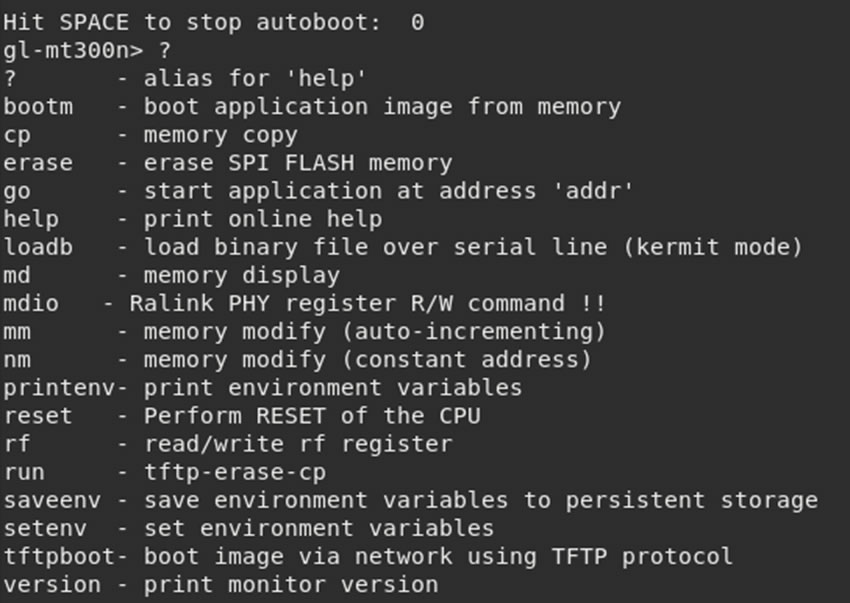
A few commands give a lot of information about the device:
The console also gives options to read areas of memory, modify values and start the application from a certain address.
There is an option to erase the SPI Flash, I’ll keep well away from that one.
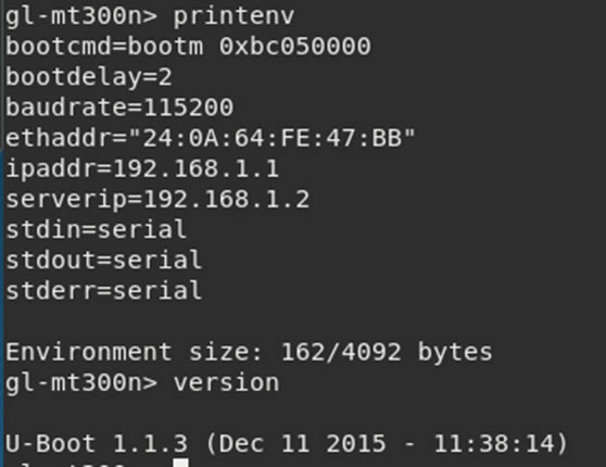
Looking at the printenv output, there is the boot location. Trying:
bootm 0xbc05000
This did what I expected, it continued with the rest of the boot sequence as per normal.
It looks like there is a high probability of bricking the device by overwriting areas of memory, so instead of poking around here, I will park this and look at other avenues.
SPI Flash
As the serial console was disabled, my next avenue attack will be to see if I can extract the firmware from the SPI flash chip.
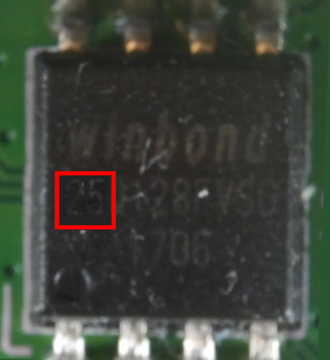
The SPI chip was identified on the board by it’s form factor and code which contains “25” which is the code for SPI flash.
SPI have got a standard pinout which can be connected straight into a raspberry pi.
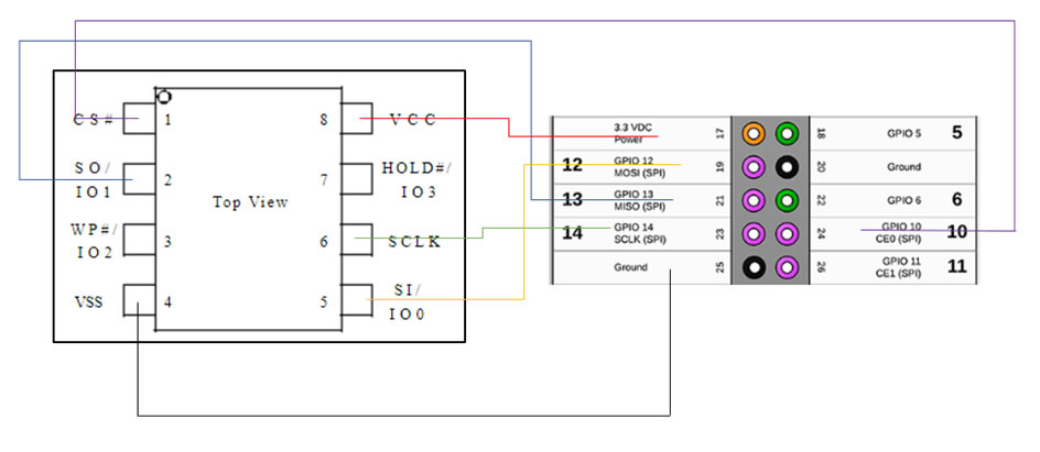
Wiring the devices up, using a SOIC8 clip directly onto the chip. This provides enough power for the board via the Raspberry Pi, however due to the Pi being connected first, it becomes the master, rather than the MCU. This allows the data to be dumped from the chip.
You will know if it’s wired up correctly as a light on the router will turn on, if this doesn’t happen, recount down the pins on the raspberry pi, as this is an easy mistake to make which I do far too often!
Flashrom appears to be unable to read the data or even identify the chip, which is weird. Finding the datasheet I confirm that the pinouts are correct.
The reason this happens is that there is contention for the SPI bus – it isn’t meant to have two masters! However, a trick to get around this is holding down a reset button while reading the flash. This stops the chip from mastering to the MCU.
Holding down the reset button led to the dump being created.
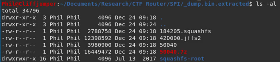
Running it through binwalk, shows that there is a squashFS and a jffs2 file system in it:
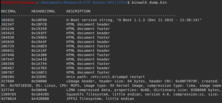
Using binwalk the files can be extracted:
binwalk -e dump.bin
It’s now possible to look around the file system and find any passwords or hints as to what to try next.
Squashfs File system
The first place to look is the passwd and shadow files within the /etc/ directory.
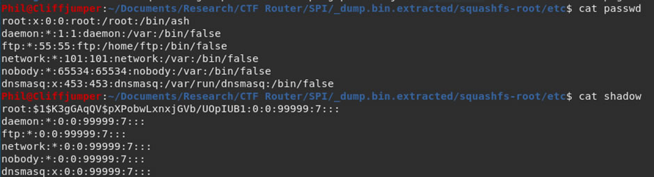
There is a single user, the superuser root. There is also a password hash, in the background I put that into hashcat to try and crack
hashcat -m 500 hash.txt /usr/share/wordlists/rockyou.txt –force
Leaving that to run, I enumerate the rest of the file system. Doing a grep for “ass” is a good way to find any easy wins, unfortunately here there were no easy wins to be had. The reason to not use “password” is it might be shortened to “pass” and the p may be capitalized (even though grep should be case insensitive using the -i flag).
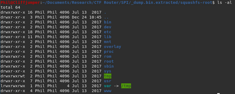
Looking through the file system using:
ls -alR
This displays all the files within the file structure:
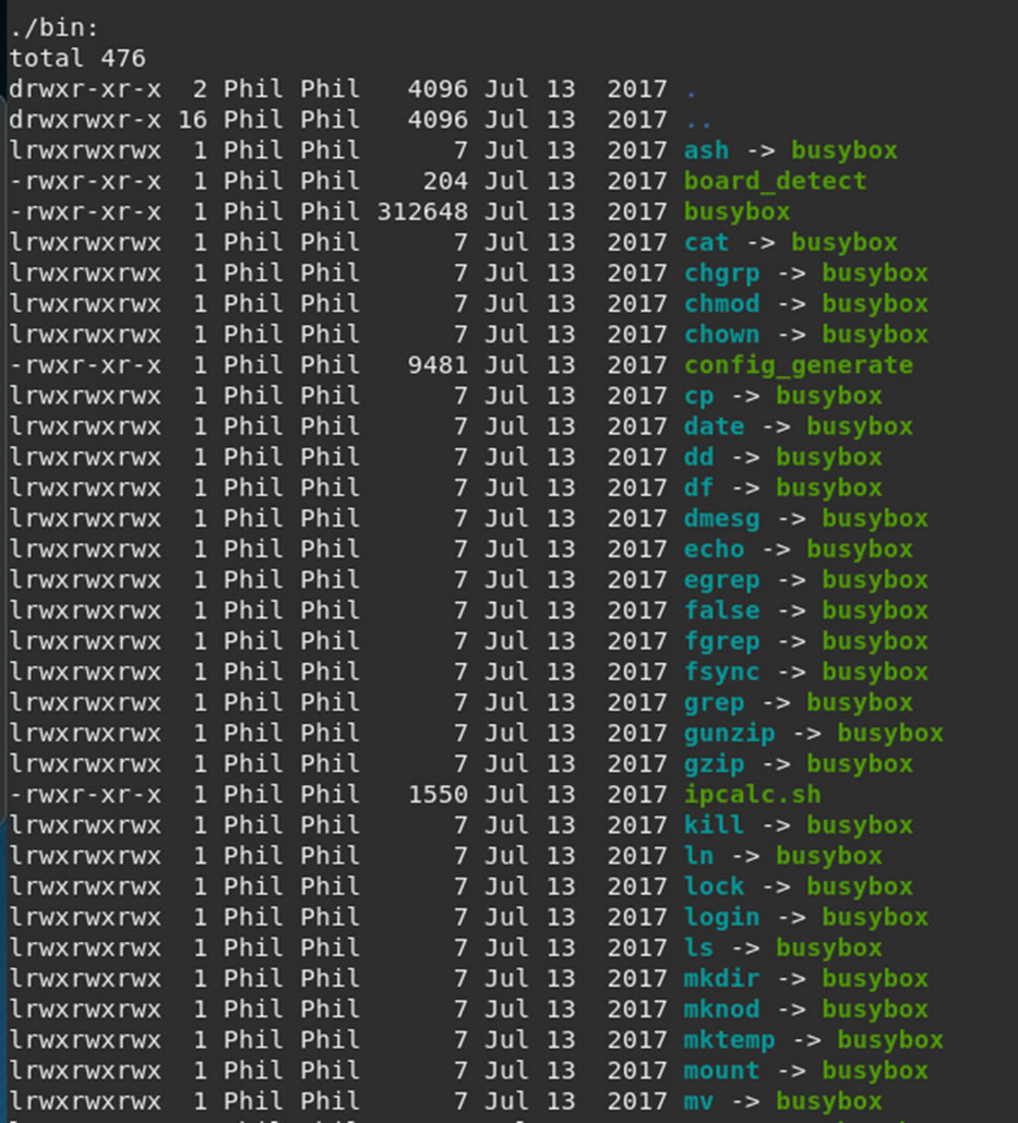
The device is using Busybox for a lot of processes.
Busybox is commonly found within IoT devices, it provides several utilities all within the single executable. However, it also has a few known vulnerabilities.
Looking through the files, there are a few to come back to:
Within /etc/:

This might tell us the full version of what is running on the router.
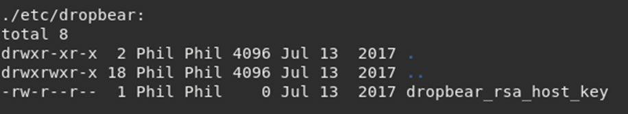
If we can get any keys, this could help connecting into the box later on, unfortunately the size of this shows it is currently empty.
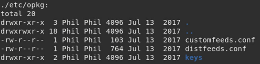
Anything with a directory called keys is always of interest.
Within /config/:

Luci is running the web application, so there might be clues to the web app password in there.
Within /lib/:
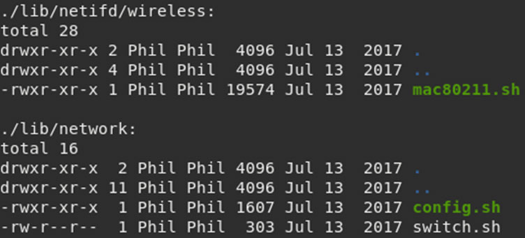
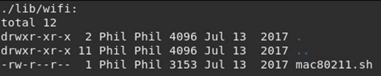
These scripts might contain useful information used during the setup.
Going through each of those files brings back some information about the device, the OS-Release in /etc/ gives a lot of information:
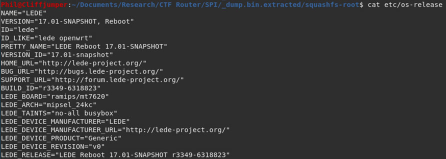
LEDE is the operating system created by the OpenWrt project.
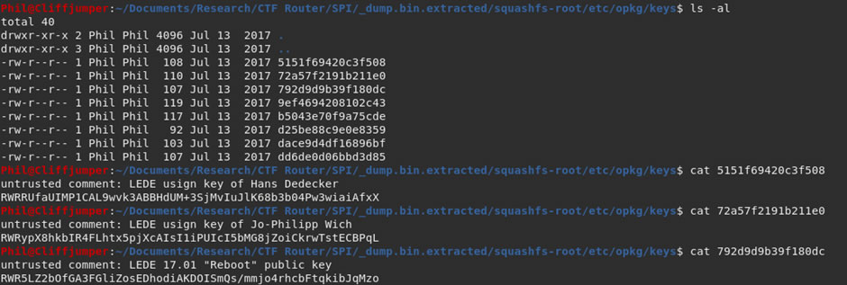
The keys within the opkg/keys directory are the public keys used by the OS, so no direct use for this purpose.
While I was hunting around the directories, the hashcat run finished:
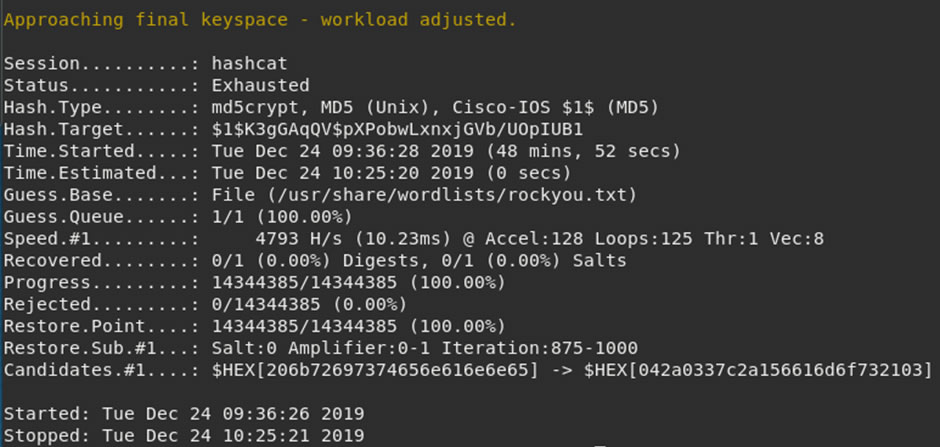
Unfortunately, no hits on the root password with hashcat and the rockyou word list.
Running the same hash through JohnTheRipper cracks it almost immediately.
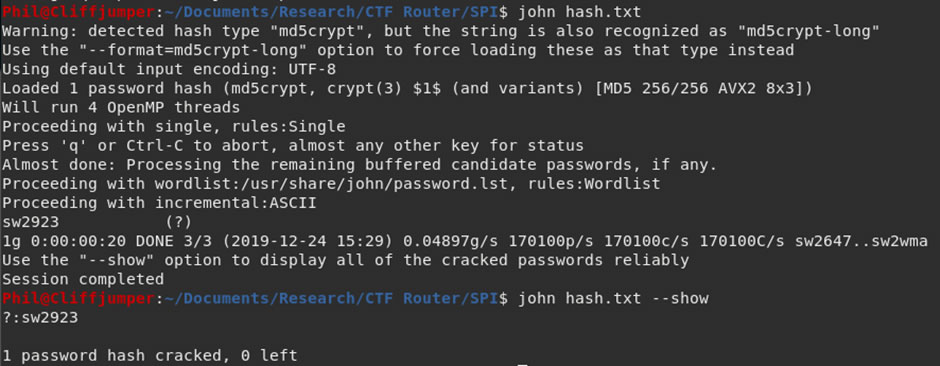
The root password is sw2923
I wonder if this is also the web application password? I know it won’t be the Wi-Fi password as it isn’t the required 8 characters.
JFFS2 File system
The filesystem I have been looking through was the squash-fs filesystem, however there is another file system on the SPI chip.
The jffs2 file system. This is also possible to be extracted using binwalk, although it requires some additional flags.
binwalk -Me dump.bin
This will recursively go through the files and extract them, allowing the program to extract both the squashfs and jffs2 file systems.
The extracted jffs2 file system looks to contain compressed data and empty folders only.
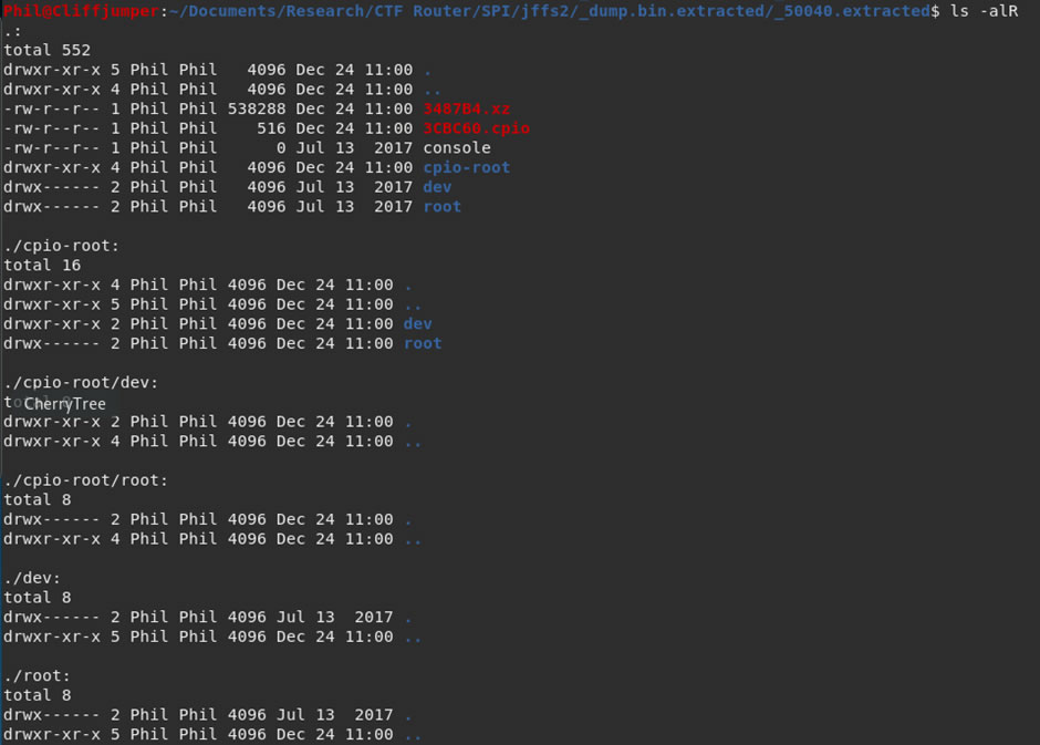
The files at the top are compressed, using the XZ compression and the CPI archive system.
Running a strings against 3487B4.xz results in some information, with what looks like might be a root password at the end:
The same result is provided by the CPIO file. I know this isn’t the root password however it could be the web application or Wi-Fi password.
Unfortunately, it is not the password for the web applications.
It was also not the password for the Wi-Fi:
There is another tool to look at jffs2 file structures which is jffs2reader, running this against the jffs2 data structure:
jffs2reader 42D000.jffs2
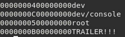
This brings back a list of files:
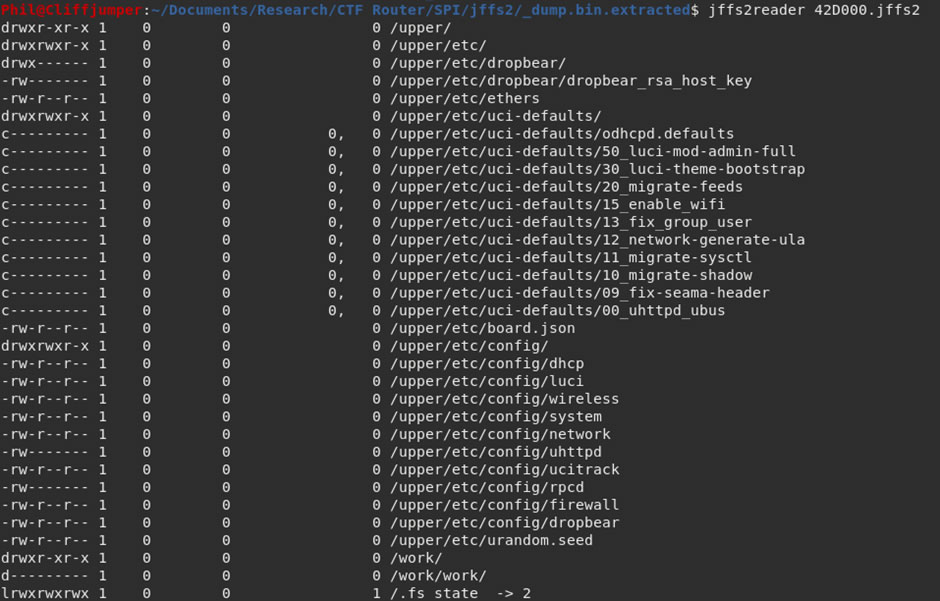
Unfortunately, without mounting the jffs2 structure I was unable to look in each file. However, the “15_enable_wifi” file looks interesting and might contain some information.
Going back to the SPI flash, I located that file and read it:
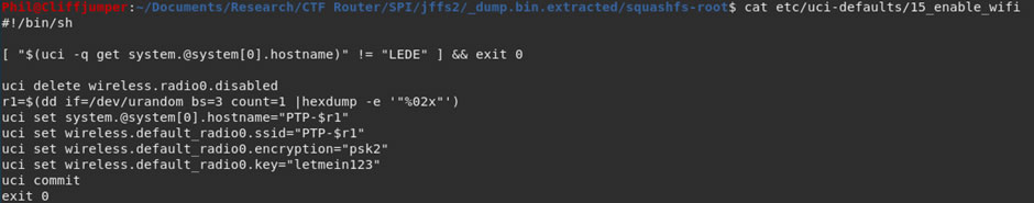
This file had all the information I needed, the PSK for the Wi-Fi is “letmein123”
Another way that would have worked better, is using Wi-Fi SSID which I knew and doing a grep through the filesystem for part of that would have got the same result:

I grepped for different terms, including “password”, “psk” and “pre-shared key”. However, searching the SSID gave much more useful information.
Wi-Fi Connected
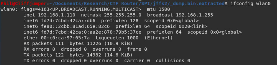
Connecting to the Wi-Fi using the password of “letmein123” provides me with a connection and an IP address.
Running another port scan against the device, returns the same 2 ports open:
There doesn’t appear to be much more to find out from the SPI flash or being connected to the Wi-Fi. Instead it might be required to go back to the board.
Web Applications
As I’m on the Wi-Fi it’s possible to check the root password on the web application. Entering the credentials:
root:sw2923
Success, password reuse of the root account and main login to the web application provided access.
Having a hunt around the web-gui there are some options which seem useful, within the Administration area there are SSH settings:
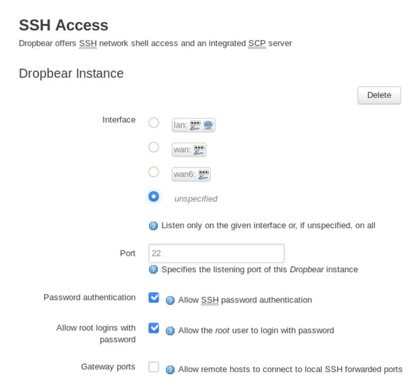
Changing the interface to LAN might open up Port 22 and allow SSH access into the device.
Unfortunately, even when set to LAN, port 22 remains closed, this must be due to firewall rules.
However, changing the Port that SSH uses to a higher port, allows direct SSH as it bypasses the firewall rules and provides access using the password that was cracked from the shadow file.
Conclusion
This was a fun little CTF, there were a number of different hardware skills involved, from checking and confirming chip information, to connecting to serial ports and accessing the uboot console. The SPI flash provided the main bulk of the information and an important skill is knowing how and where to look to find each bit of information.
There are many different routes to root, once you have access to the web-gui but understanding what is stopping a service is just as important as exploiting a different service.