This is a follow-up to my post where I ripped the software of a remote control camera tank apart. At the time I hadn’t cracked the case open. Now I’ve had time, so let’s have a look what’s inside!
Even before I dug out the screwdrivers, I suspected that there would be two boards present: one motherboard which controls the motor and camera logic and a daughterboard which is basically a wireless access point with a direct pass through from TCP to a UART connection on the motherboard.
Guess what I found? Two boards: one motherboard and a daughterboard. I like it when I’m right ☺. The tank itself is held together by six screws, which can be removed; then the connectors to the lights, motors and camera on the top of the tank can be disconnected. All connectors to the motors and batteries on the bottom of the tank are soldered in.
A note about the photos: I’m not a professional (or otherwise) photographer. These have been taken with a standard mobile phone and a cheap USB microscope and deresolutioned to be placed on a website. If you have specific questions about stuff on the motherboard contact us and we’ll help as best we can.
The Motherboard
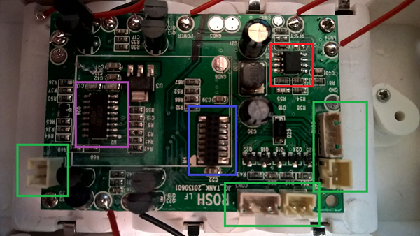
So, here’s the motherboard:
Its single sided so there’s little point in showing the other side of the board and it’s a swine to photograph as the motors and battery connectors are directly soldered on.
We can see a date on the board: 20130601 – so it’s quite an old IoT device. I’ve highlighted some parts in coloured rectangles:
Green – these are connectors to the lights, camera and camera motor on the top of the tank. The manufacturers have splashed out on connectors to make it easier (and therefore) quicker to make the whole unit.
Blue – This is the connector to the wireless daughterboard. The board is actually offset on the connector (4 pins don’t connect). The board is stabilised by a phone pad on top of the microcontroller (which I’ve removed and cleaned up for the photo).
Purple – This is the board’s microcontroller. The print on it is overdone and it’s hard to read and, no, I haven’t found out the specifics of what it is, if your Google-Fu is better than mine you may have a better success rate than me, so here’s a picture from my USB Microscope.
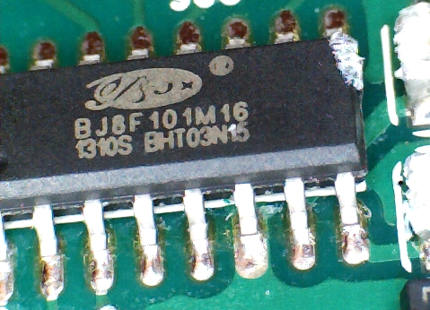
The chip number is BJ8F01M16 1310S BHT03N15 and I can’t make out the logo.
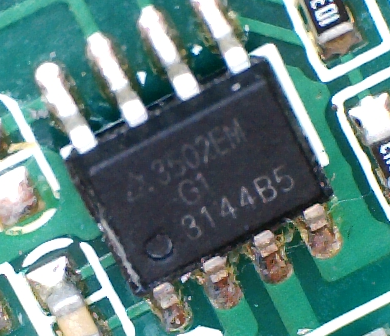
Red – Although this looks like an EEPROM chip it turns out that it’s an AP3502EM – a DC to DC convertor, presumably to drop the voltage from the 6 (!) AA batteries (That’s 9V) to 3.3 for the wireless daughterboard.
As there’s no separate memory chip, one can only assume that all logic, firmware and RAM is in the microcontroller. Finding out what this is would help a lot in hacking the device for further use.
The Wireless Daughterboard
First off apologies for the fuzziness of the photos, I could not get my camera to actually focus on the board itself. In terms of size, its height is about the same as the diameter of a 2 pence piece.
The board is double sided, first the backside:
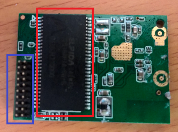
There’s nothing much exciting here:
Blue – this is the connector to the motherboard, the top 4 pins hang loose in the air here.
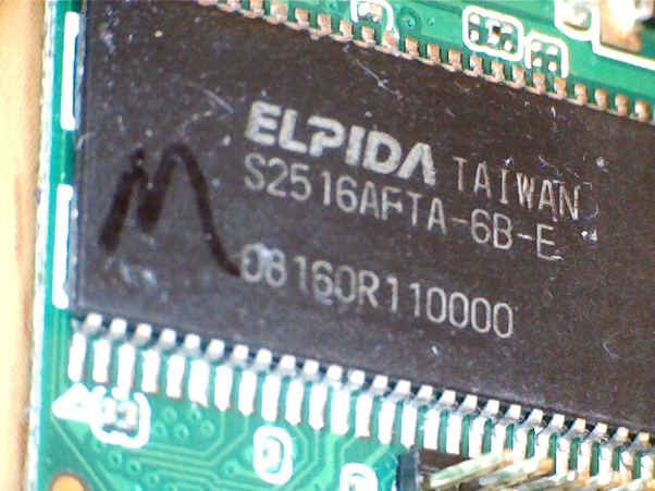
Red – This is the wireless AP’s RAM, specifically it’s an S2516AFTA-6B-E, which is 256Mbits, so 32MB of memory, which isn’t much to place our hacking tools in!
The front side of the daughterboard is a bit more interesting (but not as out of focus as the below photo shows):
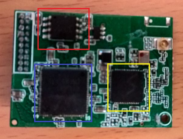
This side is dominated by 3 main chips:
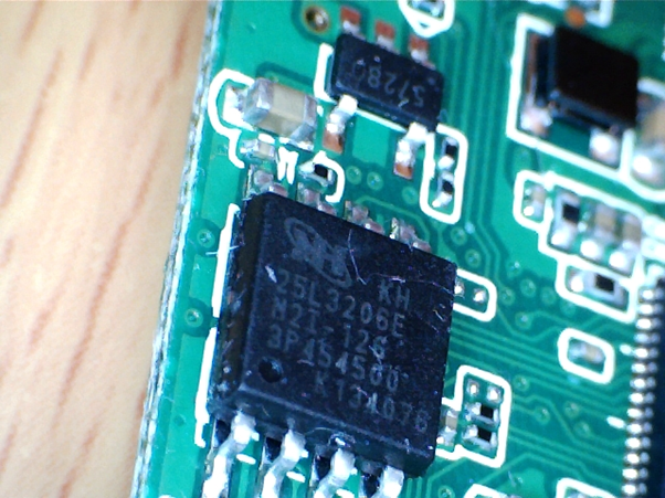
Red – This is the board’s EEPROM, it is a 25L3206E, which is basically 32 Mbit (4 Mbyte) of flash memory accessible through the SPI protocol – it’s likely that this will be used for storing transient data rather that the full file system of the host.
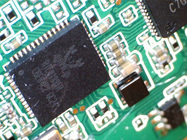
Yellow – is an RTL8188ER Wi-Fi controller – this basically does all the Wi-Fi’y bits of the circuit. The photo is particularly poor here as the etching was rather hard to see at any angle and this is the clearest photo I could get:
Blue – This is the System on Chip (SoC) – basically the CPU plus a selection of other drivers, an RTL8196EU, which is based on the Lexra RLX4181 – a MIPS clone. The Realtek datasheets require an NDA in place so I can’t find much more on this.