
Introduction
We do a lot of client work with ICS, IIoT, and SCADA. We’ve been to various power plants, factories, electricity substations and they all use the same technology in the form of a PLC. A PLC is a Programmable Logic Controller.
PLCs are what keep our Critical National Infrastructure running. The technology is old, but it works consistently pretty much all the time. It is far cry from regular operating systems which might blue screen at any moment, as this just would not be an option when running the nations electricity or water supply, or the safety of nuclear material.
Rather than anything quite that dangerous, this post is an introduction to PLCs and the ladder logic behind them, using a model of a traffic light to explain how it works and how you can recreate it at home. To achieve this we’ll be using OpenPLC, a Raspberry Pi, and a beginners electronics kit.
OpenPLC
OpenPLC is a PLC program that has two distinct parts. There is an editor, where you can create programs using ladder logic. Then there is a runtime which uses kit such as an ardunio or Raspberry Pi to run the code and uses the GPIO pins as the switches. So you can build a working circuit and see the logic happening in front of your eyes.
The software is easy to install and has great guides on its website, so this blog is going to skip over the installation steps. For this project I used a Windows 10 VM for the editor and a Raspberry Pi for the runtime server.
Ladder Logic
Before we begin, one thing about ladder logic is although it is logical, it is logic unlike any other!
The idea behind ladder logic, is you have 2 rails and rungs where stuff happens in the middle. The electrical circuit runs down the rails doing the tasks in order, however it runs through the rail so quickly (around 300ms per revolution) that you have to think of everything happening in parallel.
This adds in challenges, as if your first rung is to turn on a light and the second rung is to turn off the light. The logic doesn’t wait for the first rung to finish before moving on, it carries on down the rails. So, it would be a never ending flickering of the light and it quickly goes from off to on.
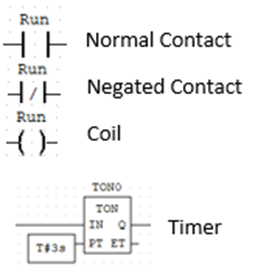
For our ladder logic project, we need to introduce some key terms:
- Contacts – These are like switches, but they are controlled by coils. If a coil is on the switch is closed. If the coil is off, the switch is open.
- However, there are 2 types of contacts:
- Regular – As described above, a coil is on the contact is made, the circuit runs
- Negated – The opposite. A coil is on, the contact is open and the circuit doesn’t run
- However, there are 2 types of contacts:
- Coils – These were originally coils of wire around a magnet to create an electromagnetic field. These then control the contacts. If the coil is “on” the contact is “on”.
- Timers – These are simple. In our project we only use the “TON” turn on timer. These are counters that keep the output false until a certain amount of time has passed. So a delay timer effectively.
The symbols for each of these are:
The idea behind ladder logic is; what needs to be happening or not happening for your thing to happen.
Therefore, can something only happen, if nothing else is happening? Or does something else need to happen so that your thing can happen. Or with timers, after 10 seconds of a thing happening your thing can happen.
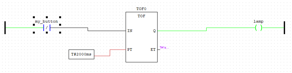
Make sense? Not quite. Ok, let’s look at the OpenPLC ladder logic “Hello World” example.
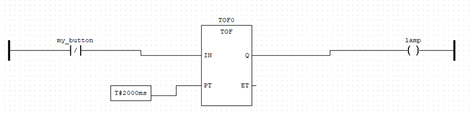
This is nice and simple. There is a negated contact going into a time off timer which then effects the lamp coil. (If you are wondering why the switch it negated, read on to “building the circuit” and it will all make sense)
The button being negated that means it is always “on” unless pressed. So the circuit will always be complete unless the button is pushed.
As long as the button isn’t pushed the circuit will be complete and the coil “lamp” will be on.
If the button does get pressed. The lamp coil will then stay on for 2000ms as the timer does its job. After that 2000ms if the button is still pressed, the lamp will go off.
The OpenPLC editor has a nice debug option by clicking the “running man” then “sunglasses”
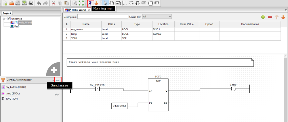
This provides a view where you can change the state of contacts. When a line, contact or coil are green it means it is powered. So when we start the button isn’t pressed resulting in full green and the counter at 0.
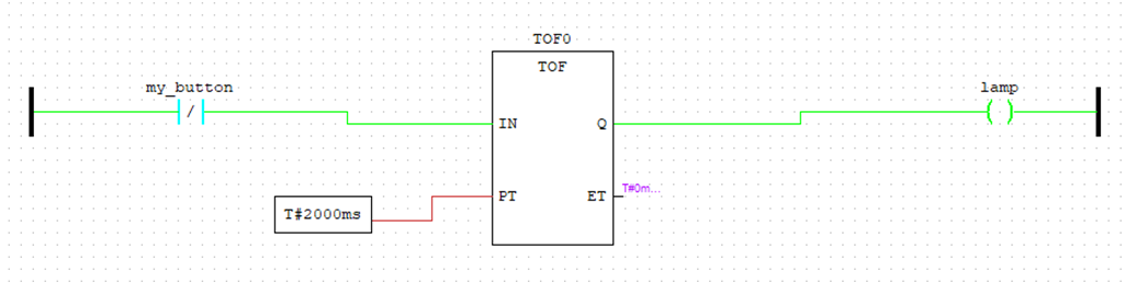
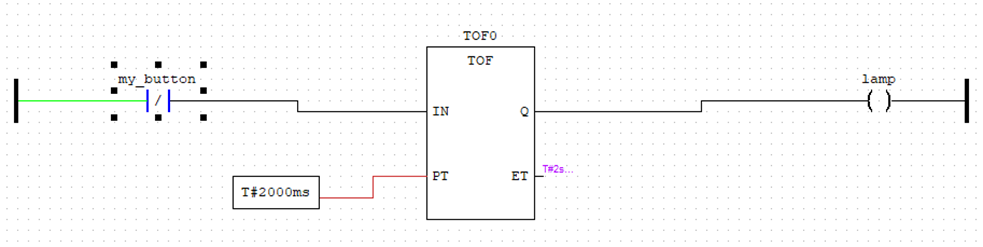
When the button is pressed, the input to the timer is black, meaning no power and the timer starts counting.
Then after the 2000ms (or 2 seconds to me and you) are over. The output from the timer becomes false, resulting in the lamp coil being turned off.
Hopefully at this stage this all makes sense.
If we wanted to export this from the editor and into the runtime server to use physical buttons and LEDs, we would need to input the GPIO which controls each function.
The pin outs are available on the OpenPLC website.
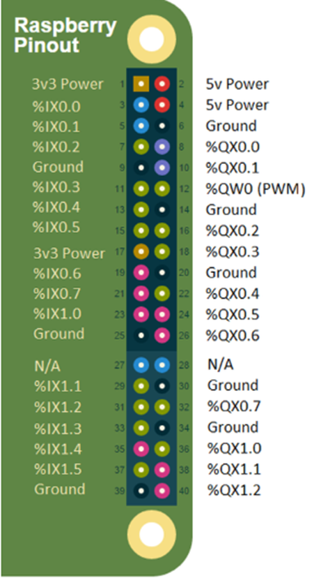
%IX are inputs (such as buttons)
%QX are outputs (such as LEDs)
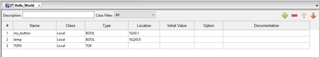
These are specified in the top of the OpenPLC editor. In this example we have the button as %IX0.1 and the LED as %QX0.0
Building the circuit
Now that we have the logic working as we wanted, we can build the circuit, all we need for this is the OpenPLC Run-Time running on a Raspberry Pi and a basic electronics kit.
First up, we need to move the program into the Run-Time on the Pi. From the Editor, we can export the program by using the down arrow
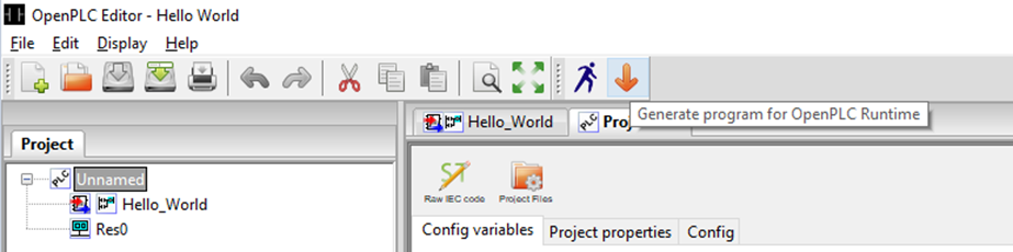
Save the file at a “.st” file. Now we need the Pi connected to that machine, so we that we can access the OpenPLC Run-Time webGUI. This is accessible on port 8080 of the Pi.
Login with the default credentials of “openplc” for both username and password and navigate to programs on the left hand side.
From there select the .st file and click upload. It will then show up in the programs.
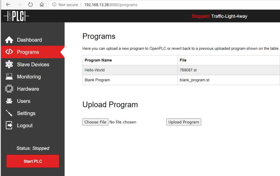
Clicking on the program gives us a few options, and we need to select Launch program. This gets the program ready so it will run when we do Start PLC.

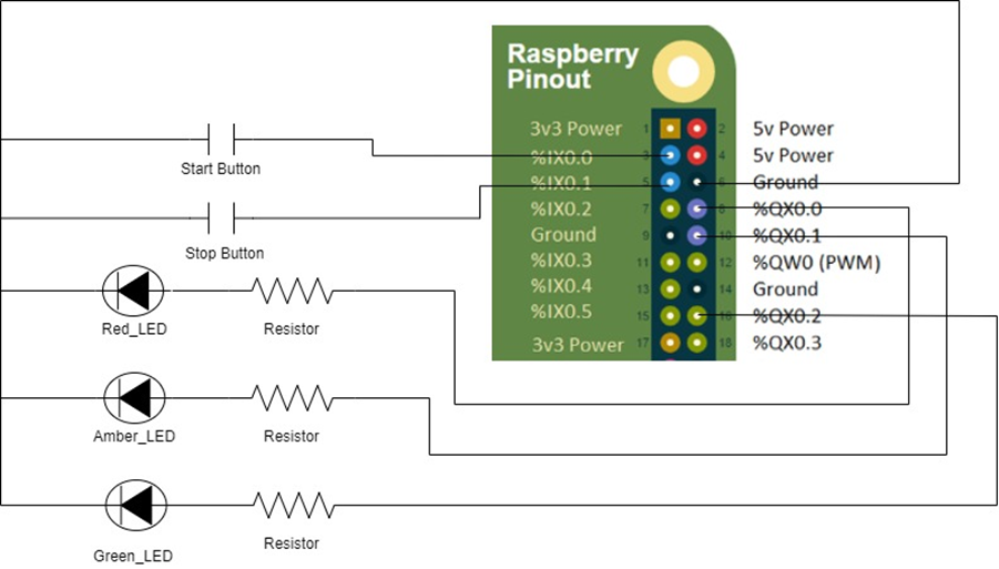
Before we start the PLC, we want to create the circuit, for this I’m using the Pi’s GPIOs, some jumper leads connecting to a breadboard with a button and LED on it.
The circuit will look like this:
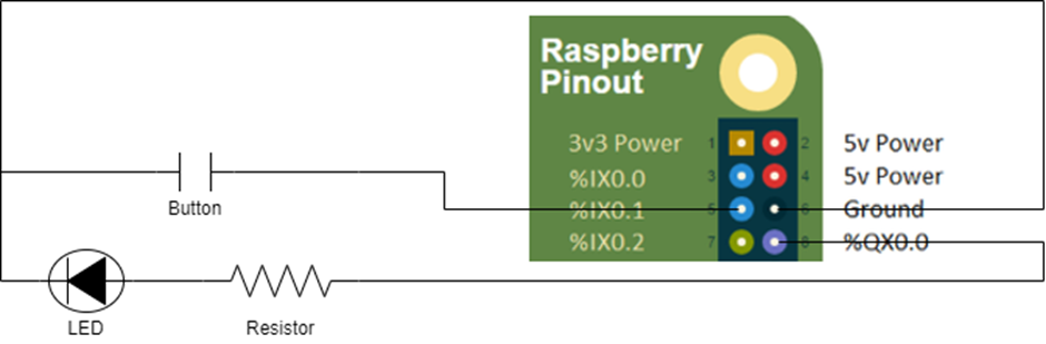
The IX0.0 and QX0.0 that we specified earlier within the program provide the power to the circuit, so we need to add these in ensuring we then have a ground back to a ground GPIO on the pi.
Plugging a resistor, button and LED into the breadboard. Then the ground is connected to pin 6 on the Pi, with the LED plugged in QX0.0 (pin 8) and the button into IX0.1 (pin 0.1)
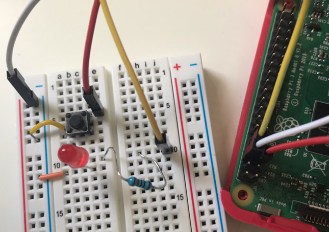
The breadboard should look similar to this:
Now that it is all wired up, back on the WebGUI, click “Start PLC”. This will start the program and if you push the button the LED should come on and stay on for 2 seconds (thanks to the TON timer).
Now you’ll remember in the debug mode, the button was negated so worked in the opposite way, now it works like a normal button. This is due to how to Raspberry Pi has its GPIOs, the pin we are using is default high and pushing the button pulls it down to low. What this means is that the default state for that pin is True which is the opposite of what we would normally need, so to combat that the button needed to be changed to negated within the ladder logic.
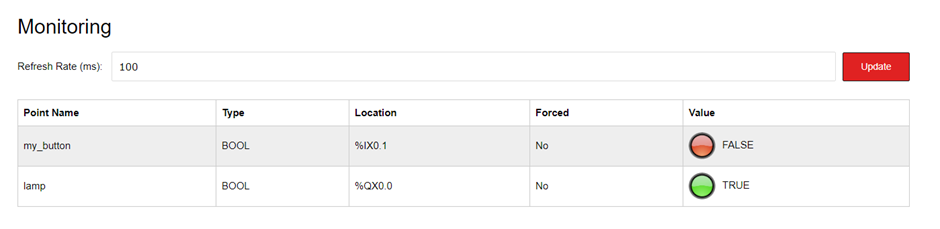
This can be seen clearer within the Run Time program, if you select Monitoring on the left hand side:
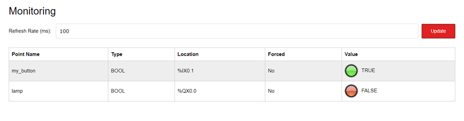
This shows that when the button isn’t being pushed, its default state is True. Pushing the button turns this to false, which then completes the circuit and lights the LED due to the negation within the ladder logic.
This is great, we now have the basics of OpenPLC, Ladder Logic and how to build it into a circuit, let’s move on the look at something slightly more complicated, a single traffic light!
Building a traffic light!
Thinking about the logic behind a single traffic light, ignoring any pedestrian crossings we have:
- Red light is on for 10 seconds
- After 10 seconds the amber comes on and both red and amber stay on
- After 3 seconds both red and amber go off and green comes on
- After 20 seconds the green goes off and the amber comes on
- After 3 seconds the amber goes off and loop back to the red being on
Simple right, a couple of timers and a coil for each light.
We also want to add in a start and stop button, just so the controller can shut it down for maintenance and start it up again.
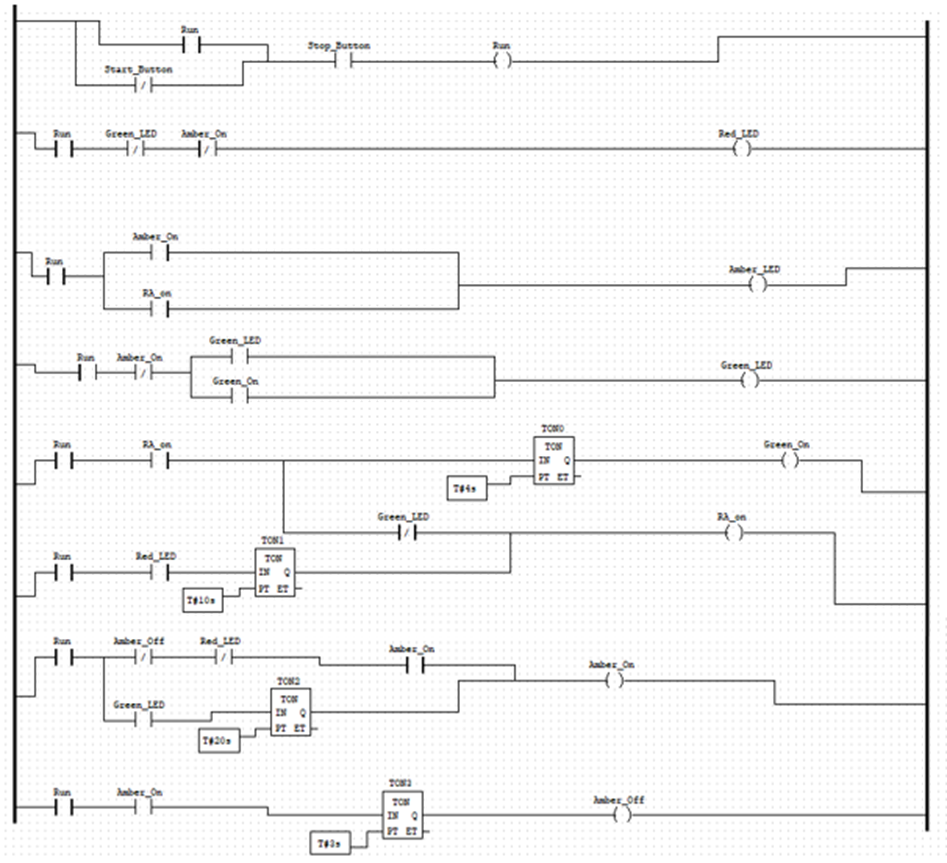
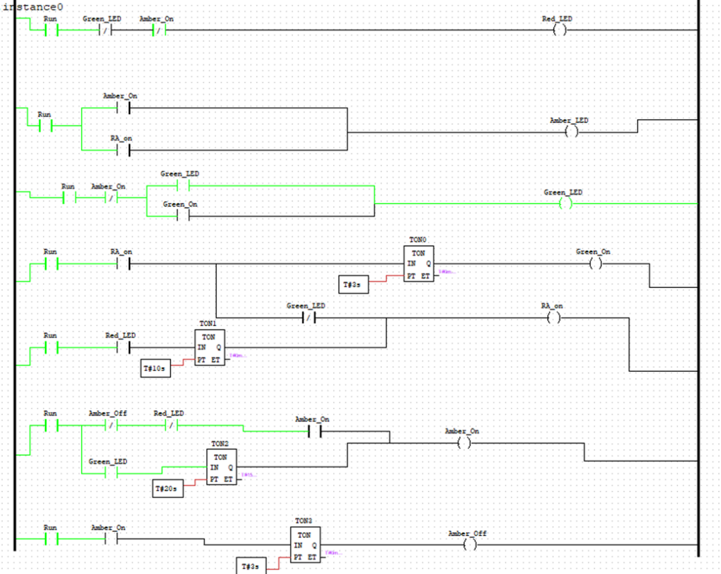
So let’s look at the code in OpenPLC editor:
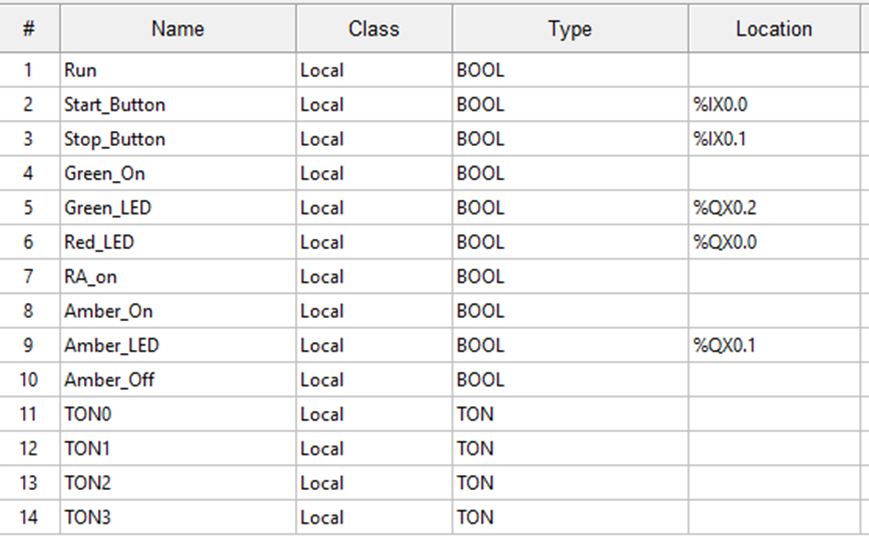
In here, we have 14 different variables! All doing an important job, if you’d like to code for this it is available on my GitHub page.
The variables in use are:
Let’s step through this and try to understand the logic for each step.
Run Function
The run function works with the following logic:
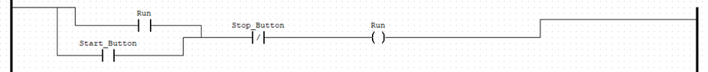
- When the Start_button is pressed and the Stop_Button is not pressed then run.
- OR if the Run coil is powered and the Stop_Button is not pressed then run.
The usage here, is an operator will press the Start_Button turning the run coil on, this then remains on due to the run contact being closed until the Stop_Button is pressed.
Red Light
We want the red light to be on for 10 seconds.

- If the Run coil is on, the Green_LED coil and Amber_on coil are off, then the red light is on.
This means, as long as nothing else is happening, the red light will be on. As soon as either Amber on or Green come on, the red LED will turn off.
The red light is one of the most complicated parts of this logic, as it not only needs to operate after the Start_Button is pushed, it also needs to loop after the Amber_LED turns off. Contact negation is one of the most complex parts of ladder logic.
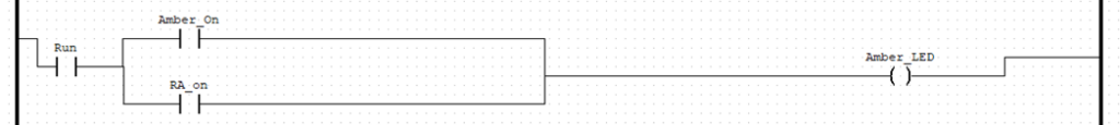
Red and Amber Lights
We want amber to join red after 10 seconds and last for 3 seconds. For this we have to introduce timers, the Amber_LED is controlled by two different coils, as we want it on during this stage and later on its own stage.
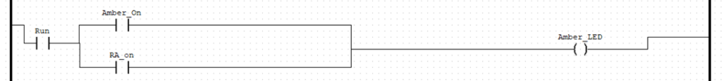
The logic here is:
- If Run and Amber_On coils are on, then Amber_LED is on; or
- If Run and RA_On coils are on, then Amber_LED is on
Looking at the RA_On logic we have:
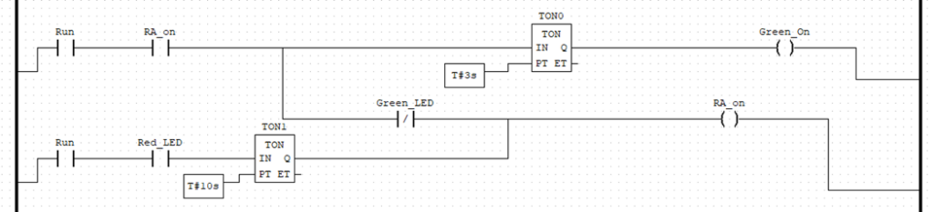
This looks much more confusing but don’t worry, we can step through this.
Starting with the second rung we have:
- If Run and Red_LED are on. The counter will start counting.
- Once the counter has got to 10 seconds. The RA_on coil will be on.
Remember that the RA_on coil completes the circuit for the Amber_LED. So this will light the Amber Light.
Then going up to the top rung we have:
- If Run and RA_on are on and Green_LED is off. Keep RA_on turned on
- If Run and RA_on are on. The counter will start counting.
One the counter gets to 3 seconds, the Green_LED coil will be on. This then breaks the circuit to RA_on via the Green_LED contact (as it’s negated) and the Amber_LED will turn off.
Green Light
We have already seen this one above. The logic for it is:
- If RA_On is turned on, count to 3 seconds then turn on Green_LED
Amber Light (without red)
The amber light needs to come on 20 seconds after the green light. However this also holds the key in looping the code.
The logic for turning the Amber light on is:
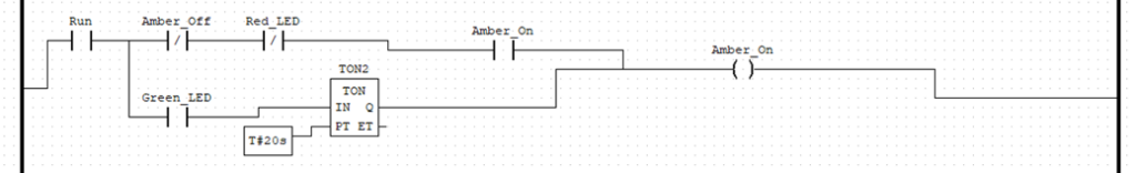
Running through this, to turn the Amber_on coil on we first need to follow the second rung:
- If run and Green_LED are on. Then start counting 20 seconds. After 20 seconds turn on Amber_On.
Remembering from earlier that Amber_On turns on the Amber_LED
The top rail of the Amber_On coil logic states that:
- If Run is on and Amber_off and Red_LED are off and Amber_On is on, then the coil Amber_on will remain on.
Effectively, if Amber_Off or Red_Led coils turn on, then Amber_On coil turns off.
Also it can’t turn on via this rail, as it already needs to be on for the whole rail to be active. If you didn’t have this part of the logic, then the coil would be on whenever Amber_Off or Red_LED were off, resulting in amber being on for the entire duration of the green light phase.
The last step to this is how we then loop back round to red. Remember how red only comes on if no other lights are on, this means we can’t turn this coil off by going to the next light like we have previously, we need to specifically turn the Amber_On coil off.
Amber_Off
This is quite straightforward, once Amber_On is active, we want the light to stay on for 3 seconds, then turn off (and by turning it off, turns on red as nothing else is active)
Even though this seems simple now, when starting out looping logic is very confusing due to the logic of red only running when nothing else is.
The ladder for this is:

The logic here shows that:
- If Run and Amber_On coils are on. Then the timer starts counting up 3 seconds. After 3 seconds the Amber_Off coil is on.
This coil then stops the Amber_Light, resulting in the loop starting back to the Red_LED and it carries on until the Stop_Button is pushed.
Debugging
It was required to debug a lot throughout the process of this. Using the running man and sunglasses we can see the cycle running. If it gets stuck anywhere try and explain the logic in words and see which coil is on or off incorrectly for the next step!
Remember the green lines, contacts and coils show what is currently powered. So we can see that Green_LED has power, via the Green_LED contact. We can also see that as the Green_LED is on, there is power to the timer and the time next to it shows 15 seconds have passed. Once that reaches the target of 20 seconds, the Amber_On coil will turn on, which will turn off the Green_LED by the negated contact of Amber_On.
Now that the ladder logic has been built and successfully debugged, we can follow the same steps as earlier to move it across to the Run-Time, using the editor to export the file. Then in the Run-Time webGUI import the program, click on it and press launch program.
Wiring up a breadboard and Raspberry Pi
The wiring up of this is very similar to the test project earlier, just with an additional input and two extra outputs.
The circuit for the single traffic light is:
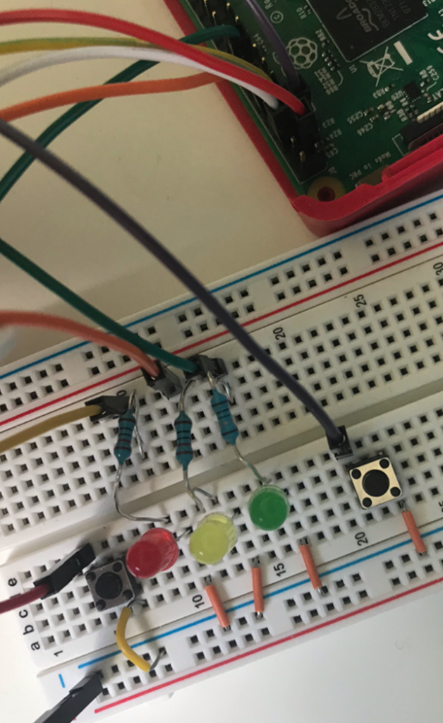
When wired up onto the breadboard, it should look similar to this:
Now when you click the start button, an endlessly looping traffic light should be running!

Success!
Getting this going was really satisfying, so much so that I created a short video of it all working which is available on my Twitter.
Next Steps
This tutorial should be enough to give you an understanding of ladder logic. The next challenge is to build the junction up to have 3 or 4 sets of traffic lights working in a loop. This involves a lot more variables and more logic, especially to get the non-looping lights to remain red, however you should now have enough knowledge to be able to work this out.
If you get stuck, feel free to either ask me questions on Twitter (@Yekki_1) or if you are really stuck, the code for a 4 way traffic light is available on GitHub.