TL;DR
How does the Tesla Model S update its firmware? What did we find when reverse engineering the display and instrument cluster?
Here’s the result of a couple of weeks work, working on a real vehicle that (mostly) worked after we had finished.
Part 1: analysing the hardware, complete with a 14 layer PCB in the CID
Part 2: reversing the firmware update process & the importance of Suicide Bomber mode
We’re publishing now as the process has recently changed with the Model 3
Overview of the Tesla Hardware
Like many contemporary vehicles, the Tesla has been constructed with multiple segregated CAN buses connected via a CAN gateway. There is a powerful embedded computer with Internet connectivity on the other side of the gateway controlling firmware updates for all of its components.
What are the physical components of the Tesla?
- CID (Central Information Display) – the large console at the centre of the dash
- IC (Instrument Cluster)
- Conventional CAN connected ECUs
Let’s take a look at the individual components
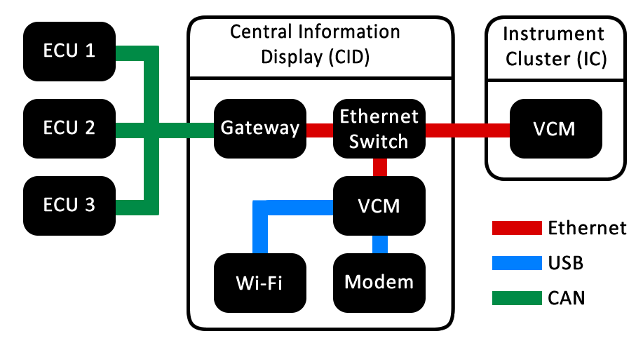
The highly integrated CID comprises:
| Wi-Fi and Bluetooth |
| Gateway interface between VCM and the various CAN buses |
| Full-sized 4GByte SD card connected to firmware gateway |
| Nvidia VCM (Visual Computer Module); ARM-based single board computer, with integrated 2 GB RAM, 8 GB NAND flash, 64MB NOR flash, and various peripherals |
| Ethernet switch |
| 16GByte microSD connected to VCM for mapping data |
| 3G modem for cellular connectivity |
| Assorted other modules including FPGA for display glue logic |
Most vehicles have separate units for IVI (in-vehicle infotainment), CAN gateway and TCU (telematics control unit), but the Tesla combines the central information into one single, large unit. On other cars, the IVI, CAN gateway and TCU are generally all produced by different manufacturers (e.g., a Clarion IVI, Bosch gateway and Ficosa TCU). The Tesla integrates these units for full control over implementation, which partly explains why changes can be made so quickly.
The CID and IC are connected by both Ethernet and CAN bus. The IC is quite basic, the only security relevant component being another Nvidia VCM. This differs from the one in the CID, and has 50% less RAM. The CAN connected ECUs are more generic in the rest of the vehicle and are generally microcontrollers with integrated flash, running bare-metal software or a RTOS (real-time operating system). They have been produced by various manufacturers – some similar or identical to those found in other vehicles, while others (e.g., the Body Control Module manufactured by Pektron) are custom-made.
CAN buses found in the Tesla:
| 1 – dedicated connection to diagnostic OBD-II port |
| 2 – body – door, lights, mirrors |
| 3 – powertrain – drive inverters, battery management system, charger, thermal controller |
| 4 – body – climate control, seats |
| There is no ‘5’ – although the hardware is present on the CID it is not used. |
| 6 – chassis – suspension, instrument cluster, stability controller, power steering |
The Tesla also has a number of LIN buses.
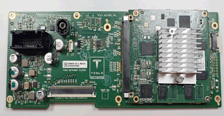
CID Hardware Architecture
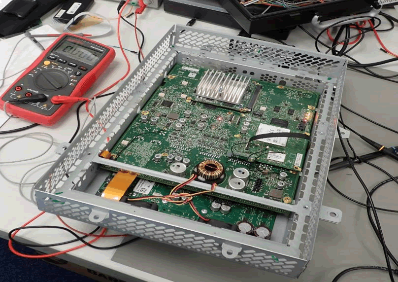
The CID is rather complicated. A 14-layer PCB unites several functional blocks.
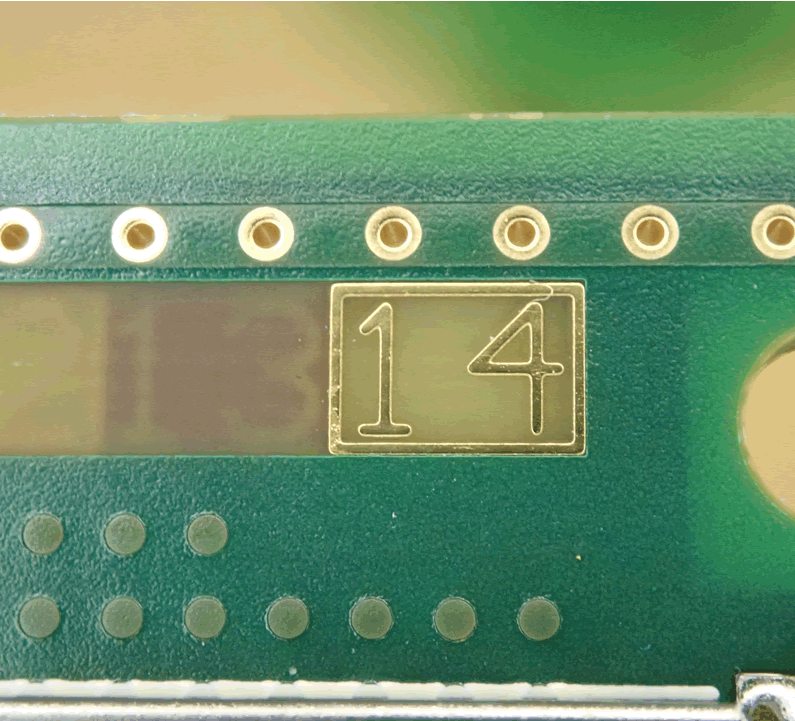
This makes it tricky to reverse engineer, not least because of a lack of public domain information. Damage to the CID would make the vehicle inoperable.
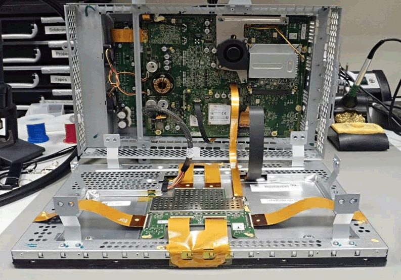
We took the CID out of the Tesla to power it up and examine it.
Visual Compute Module
An NVidia VCM (Visual Compute Module) sits at the core of the CID. This is an ARM based single-board computer module that runs Linux – the operating system that drives most of the visible actions of the Tesla.
Nvidia VCM modules are used in both the CID and IC.
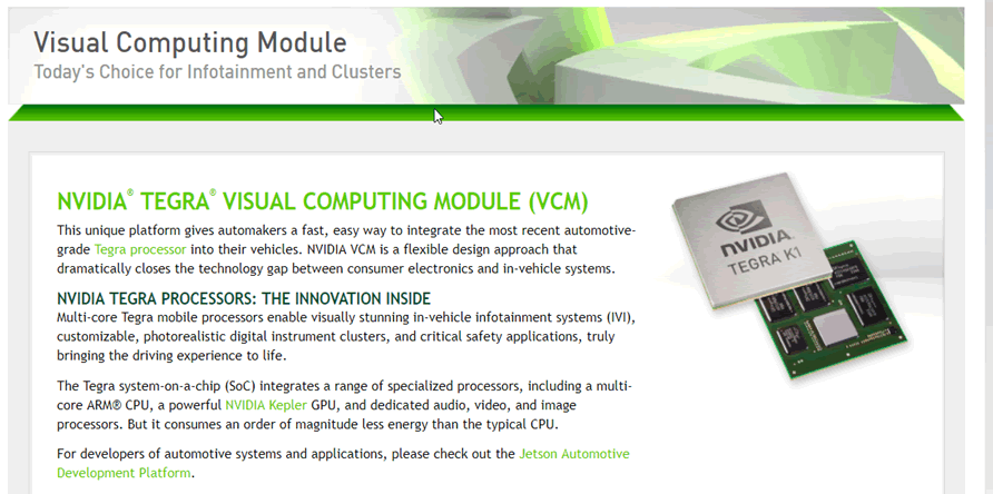
Audi, BMW and Lamborghini have all been associated with Nvidia VCMs. For example, we uncovered a similar module in an Audi Virtual Cockpit.
An Nvidia Tegra System-on-Chip (SoC) is used in the VCM. This has a multi-core ARM processor, GPU and various other audio and video accelerators. It is significantly more powerful than SoCs used in other IVIs that we have examined, which is probably due to the large CID display. The Tesla Autopilot (AP1 and AP2) uses single-board compute modules. These are very different to the VCMs in the CID and IC. This vehicle did not have a Tesla Autopilot module, so we could not test it. We did not find any significant reference to the autopilot in any code on the CID.
The VCM has no public datasheets, which is common in automotive electronics, and makes reverse engineering very difficult. This is particularly so when there is only a single unit available to test, and means that great care must be taken not to damage it. A similar VCM module is used in the “Jetson Pro Development Kit”:
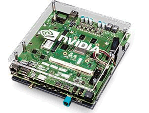
Even without direct manuals for the VCM or Tegra SoC, development boards often contain schematics and pin-outs for supplied modules, and spares for destructive tests. This would be really helpful in reverse engineering VCMs in the Tesla. Unfortunately, the Jetson Pro Development Kit does not provide any public documentation. Although we tried to obtain a development kit from eBay, there were none available when this report was prepared.
However, a similar development board, the Jetson TK1, is readily available. This does not use a VCM module, but rather directly mounts a different Tegra SoC to the PCB. The documentation for this yielded a small amount of information about the Tegra SoC. You can obtain technical reference manuals for the Tegra 2, 3 and 4 SoC lines, but they don’t contain ball-maps or pin-outs, so are of limited use for reverse engineering.
To gain access to documentation and forums, a valid developer account was created for Nvidia.com, but we could only find one reference for VCMs or the Jetson Pro development kit. We wrote a forum post asking about documentation but got no response. We envisage that an NDA would have to be signed to gain access to anything significant but it is unlikely that we would be able to share any of the information with third parties.
The connector on the VCM is like the MXM, used for some graphics modules from laptops, which have a standardised pin-out. However, the pin-out for these modules did not resemble the VCM. We looked into other Tegra-based single-board computer modules but could not see any similarities. Different connectors, external memory and peripherals are used. We did not find anything of significance. Several news stories (including https://electrek.co/2017/09/26/tesla-intel-power-infotainment-system/) reported that Tesla were changing the Nvidia based platform to Intel. Apparently this new board is called “Gordon Lake”, and looks rather like the Nvidia VCM:
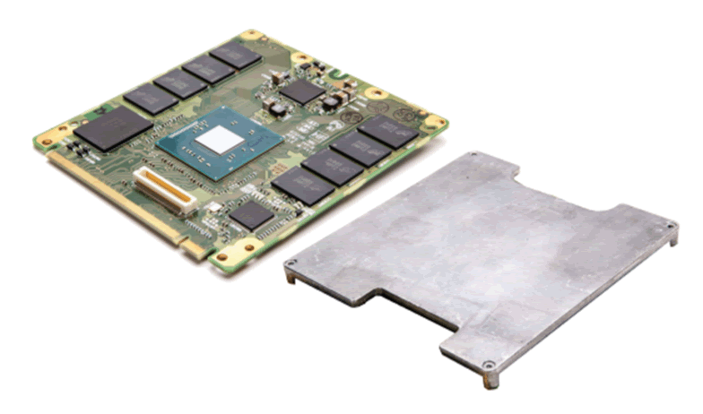
The connector seems to be identical, while the mounting arrangements look different, especially regarding use of a heat-spreader plate. As before, we were unable to obtain datasheets without entering an NDA.
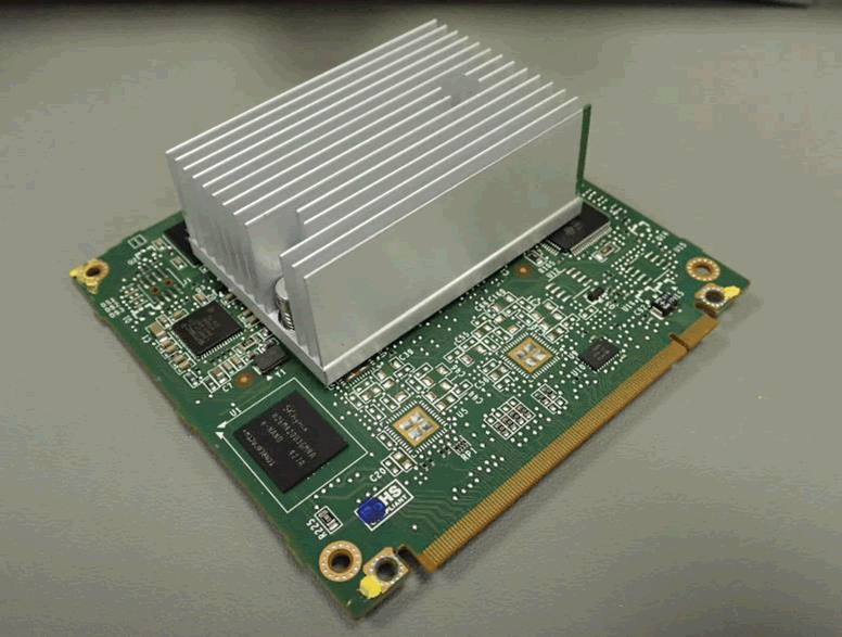
To further reverse engineering, we took out VCMs from the CID and IC for inspection:
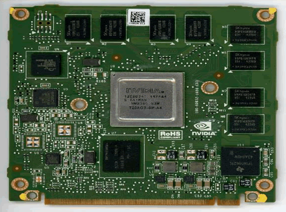
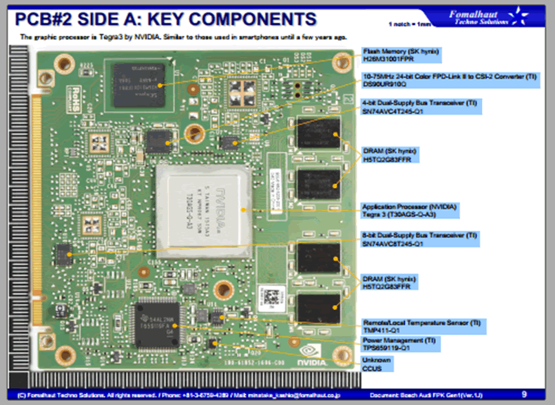
These are the major components seen on the VCM in the CID:
| An unpopulated 8-way header, J1 |
| An unpopulated footprint for LQFP100 package – the purpose of which was unclear |
| TI power management unit TPS658629I |
| Nvidia Tegra SoC T301QS-P-A3 – this part number, like many microcontrollers and SoCs for automotive applications, is not listed anywhere, and may be a proprietary Tesla part. One can assume that this is a Tegra 3 SoC. |
| SK Hynix 8GiByte eMMC NAND Flash H26M42003GMRA – the main persistent storage on the device |
| SK Hynix 4GiBit DDR3 SDRAM H5TQ4G83AFR – there are four, giving 2GiByte of RAM. This will be shared for general purpose use and graphics. There are four unpopulated footprints which could be used for further RAM. |
| SMSC USB to Ethernet controller LAN89530AM – for the Ethernet connection out to the switch |
| SMSC Automotive USB transceiver USB83340 – for USB connections out to the rest of the CID |
| Spansion 64Mibyte NOR Flash GL512S11DHA02 –storage for the kernel and bootloaders |
The VCM in the IC is very similar:
| An unpopulated 8-way header, J1 |
| An unpopulated footprint for LQFP100 package |
| An unpopulated footprint for TSOP48 package (most likely parallel NAND flash as an alternative to eMMC) |
| TI power management unit TPS65829I |
| Nvidia Tegra SoC T20AGS-SH-A4 – a Tegra 2 not a Tegra 3 in the CID; this is probably because the screen is smaller and requires less power. |
| SK Hynix 4GiByte eMMC NAND Flash H26M31001FRP1 – 50% less than the CID |
| SK Hynix 1GiBit H5PS1G83KFR – there are eight, giving 1GiByte of RAM, 50% less than the CID |
| SMSC USB to Ethernet controller LAN89350AM |
| SMSC Automotive USB transceiver USB83340 |
| Spansion 64MiByte NOR Flash GL512S11DHA02 |
We believe that the pin-outs of the two VCMs were the same – voltage supply and ground appeared to be on the same pins, which was confirmed with an oscilloscope. We did not want to direct test the VCMs from the Tesla due to risk of damaging or bricking the CID or IC. This could make the car unusable, and cost somewhere between £3,000 and £10,000 to have repaired by Tesla.
To this end, we obtained a third VCM from a second-hand IC. This was the same as the VCM in the IC from the test, except it had 50% less RAM. The IC itself was a different model. We conducted invasive testing:
Not much was gained from invasive reverse engineering.
The stage 1 and 2 bootloaders, kernel, and other boot related data are contained in the 64MB NOR flash and most of this is backed up in a primary/recovery mechanism to allow the device to boot into a recovery mode.
The remainder of the filesystem is in the 8GiByte NAND flash. Most files are stored in a compressed, read-only, file system (squashfs), with small portions stored in a read/write filesystem (ext4). This is common and allows (mostly) unchangeable files, for example system binaries, to take up a small amount of flash, with settings and logs stored uncompressed.
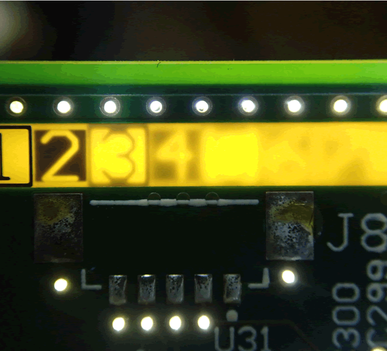
Ethernet Switch
A built-in Ethernet switch connects the VCM to the rest of the vehicle via a Marvell 88E6061. This five-port 10/100 switch supports VLANs. It is configured using SMI, a serial interface. The Ethernet switch is configured when the CID starts. A logic analyser could sniff the SMI commands. We could not ascertain whether they were sent by the VCM or the gateway processor. Traffic is segregated from the various components using several VLANs.
There is no security functionality associated with the SMI, for example integrity protection – it trusts all signals, meaning that communications can be tampered with or modified. VLAN configuration could be modified in this way, potentially creating new routes into the system. Next to the switch are 5 LEDs, indicating link/traffic on the Ethernet ports. LQFP packaging provides easy access to signals.
Gateway
This uses a Freescale SPC5668GVMG, a PowerPC-based microcontroller with 2MB flash memory and 512KB of RAM. Full datasheets are available.
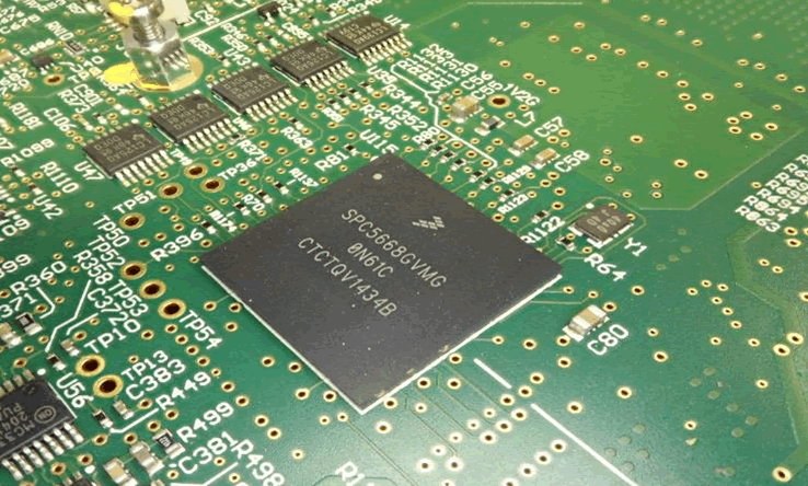
Here we show the gateway with CAN transceivers. Similar devices are often found in CAN gateways. The gateway is connected to the CAN buses and the Ethernet switch. We believe the firmware on the gateway is FreeRTOS, a light-weight real-time operating system (RTOS) with multiple automotive uses.
Cellular Modem
Sierra AirPrime AR8552 is a common choice. Mounted on a daughter board, it sits next to the GPS receiver module, a ublox LEA-6R-0-002, and an accelerometer:
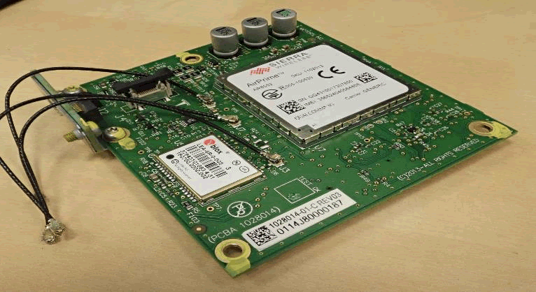
Internally, the AR8552 uses a Qualcomm MDM6200 SoC. These generally run an embedded Linux distribution called Legato. A USB is used for the cellular modem and VCM to communicate with each other.
The VCM does not contain a SIM card, unlike previously documented US Tesla modems. It is mounted instead in a remote pod and a cable connects it to the CID, so the SIM card can be accessed and changed without removing the CID. This could be due to EU competition laws, to ensure that the Tesla can use multiple mobile networks:
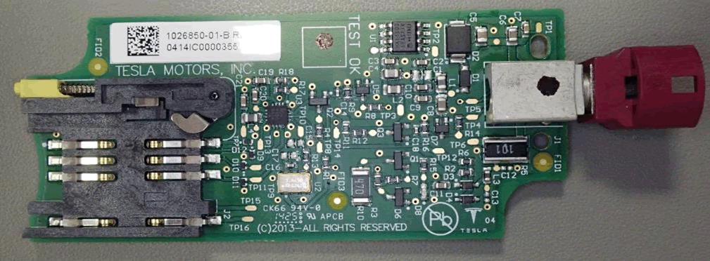
In this case, the SIM was an O2 one. We could not tell whether the SIM came with the vehicle or if it had been replaced. The SIM contained no data of any interest, such as SMS messages. The modem worked with an EE SIM.
Most TCUs in vehicles do not allow user-accessible and swappable SIM. Embedded or inaccessible SIMS are becoming the norm. Despite further examination of the Tesla, we did not uncover any functionality for tracking or eCall running on the CID’s VCM. This suggests these safety and security features run directly on the cellular modem, as per TCUs in other vehicles.
Recovering firmware from a Sierra Wireless AR8522 module without causing damage is extremely difficult, being as it is a tightly packed BGA module with numerous BGA chips, all contained under a soldered-on shield
Wi-Fi Module
The CID employs a Parrot Wi-Fi and Bluetooth module, mounted face-down. We could not confirm the specific model because it could not be removed from the main board. A Parrot FC6050W has been revealed by previous CID teardowns. The VCM and Parrot module communicate via USB.
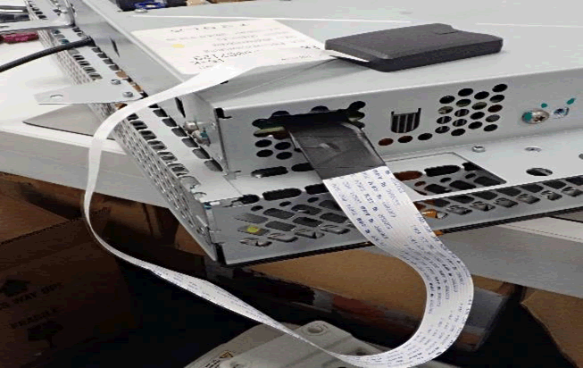
SD card storage
On top of the CID main board are two socketed SD cards. A slot in the top of the CID allows access to a 16GB microSD card which is connected to the VCM and has mapping data:
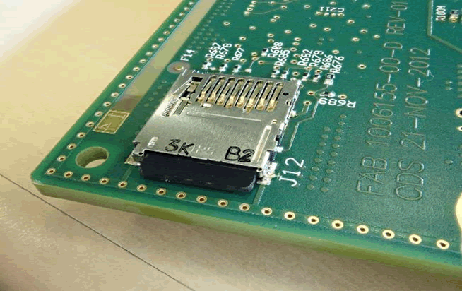
The CID has to be taken apart to access a 4GB normal SD card. It is connected to the gateway and used for staging files during the firmware update. Both were extended outside the CID during the reverse engineering so that they could be accessed with ease when the car was running.
No integrity protection or encryption was seen with either card.
What about other components?
Other components on the CID less relevant to security:
- Analog Devices ADSP-21489 DSP chip, probably used for audio playback and recording. An LQFP package is connected to an external serial flash chip
- Altera Cyclone IV EP4CE40F23A7N FPGA connected to two ISSI RAM chips and a serial flash chip for the bitsteam (essentially FPGA firmware). This probably allows the VCM to interface with the display and touch panel used for display “glue logic”.
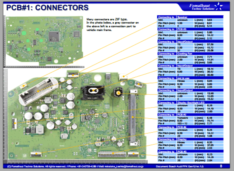
Connectors
We have not mentioned all the CID connectors here – only those we judged to be relevant to security.
External USB
There are two USB ports on the back of the CID. These seem to act in the same way; both accepting media devices and displaying them in the UI. We tried the USB peripherals, i.e., Ethernet adapters and keyboards:
- As is common on Linux based IVIs, USB Ethernet adapters enumerated, but did not function – we could not see any TCP/IP traffic.
- Keyboards enumerated but did not function
Internal USB
There is a single USB port on the CID main board connected to the VCM. Previous investigation (https://blog.lookout.com/hacking-a-tesla), discovered this could be used to gain access to a Tegra recovery mode (RCM). This had not changed; it cannot be disabled. This was still protected by security meaning that commands have to be signed before they are accepted.
The Fusée Gelée vulnerability was found in the RCM bootloader in 2018. Malicious USB packets could bypass security as a result. We confirmed with the researchers who discovered this vulnerability that it is likely to be present on the earlier Tegra SoCs used by VCMs in the Tesla. We decided not to try and exploit this vulnerability due to the risk of rendering the VCM inoperable.
Ethernet ports
On the CID, two Ethernet ports are exposed, using proprietary automotive connectors. Previously fully open, one is a dedicated diagnostic connector. This is now secured via a proprietary handshake and has no known vulnerabilities. A “seed” is sent from Tesla servers to and from the CID via VPN connection.
The CID and IC are linked by the other ethernet connector. An Ethernet switch could intercept this and sniff the traffic. Any vulnerabilities in this area have now been closed off. Where Tesla vehicles have autopilot, the diagnostic ethernet connector is repurposed, and has a diagnostic port.
Conventional diagnostic connectors
There are two more conventional diagnostic connectors. An OBD-II port provides access to CAN bus 1 and 6. There is a special diagnostic port for access to CAN bus 2, 3, 4 and 6, and the K-Line bus used uniquely for HVAC. No sign of segregation or access control was observed – if someone had access to this port they could sniff and send arbitrary CAN traffic.
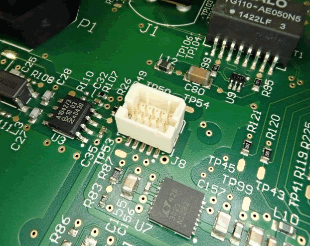
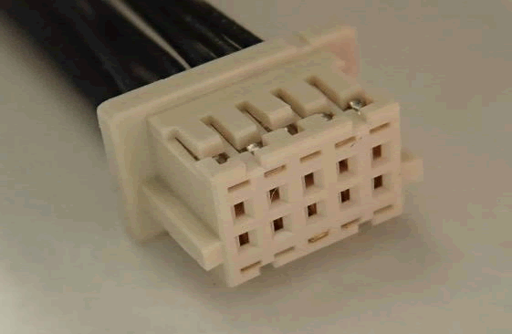
JTAG headers
Various embedded devices can have firmware recovered and be attacked by JTAG – a debug protocol. JTAG functionality is present in multiple devices of the CID and IC. Other Tesla enthusiasts told us they have been locked. In terms of the physical JTAG connections, multiple 10pin headers have been fitted on both the CID and IC main boards. It looks like they may be JTAG connections because these are all near microcontrollers or memory devices:
Several methods are available to determine the pin-out:
- Brute-force JTAG testing (“JTAGulating”) – can produce false positives and damage the board
- Continuity tests to known JTAG pins on one of the devices are reliable if pins can be accessed and datasheets are available
The only package with accessible pins and JTAG is the Analog Device ADSP-21489 – the rest are BGA. The JTAG connector pin-out could be determined because the datasheet and pinout were available. We used social media to identify and order the specific type of connector. We made a cable and used a variety of JTAG adapters and a logic analyser to ascertain if any security had been enabled.
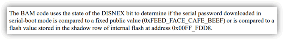
We tried JTAG commands but the VCM on the CID and IC did not respond, leading us to think that it is likely that access is prevented due to blown SoC fuses. Using the “censorship” functionality provided by the MPC56xx series, a JTAG ID elicited a response from the gateway processor. This uses 64bit password protection. We tried the default value of FEEDFACECAFEBEEF without success. We ruled out brute-forcing this; firmware could be obtained using other methods.
JTAG ID elicited a response from the ADSP-21489, but it seemed to be using 64bit password protection. This proprietary protection scheme requires a specific JTAG adapter. This would cost about £1,200 and probably merely confirm that access is not possible. We believe it would be unlikely to pose any immediate security risks.
JTAG Secure was blocking access to the Altera Cyclone IV FPGA. There are no known security issues. We did not perform checks against the Parrot Wi-Fi board, since no datasheets are available and there is a low security impact. We were pleased to see all JTAG access closed off since many systems allow access.
Read Part 2: reversing the firmware update process & the importance of Suicide Bomber mode