Sometimes, the mobile devices we work on only have cellular data connections. In those instances, we’re usually pretty interested in trying things like this to get credentials for the APN so we can start snooping around on that. We’re also really interested in monitoring what kind of traffic is coming out of the device, and whether there’s anything interesting going on.
So – it’s important we get control over the SIM card without trashing the stock SIM.
If the device uses normal SIM cards it’s really simple to pop out the old one, and replace the card with our own (which will then cause the device to connect to our – very useful – Sysmocom 3G “Network in a Box”).
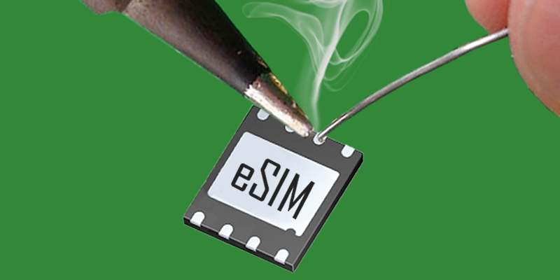
However, sometimes you come up against eSIMs (Embedded SIMs). At the moment these are usually MFF2 eSIM cards, in something like an 8-pin QFN package (although strictly speaking, they’re DFN-8 or SON-8 package).
These are becoming more common for connected devices and are slightly less trivial to replace than the old-style “SIM in a caddy”.
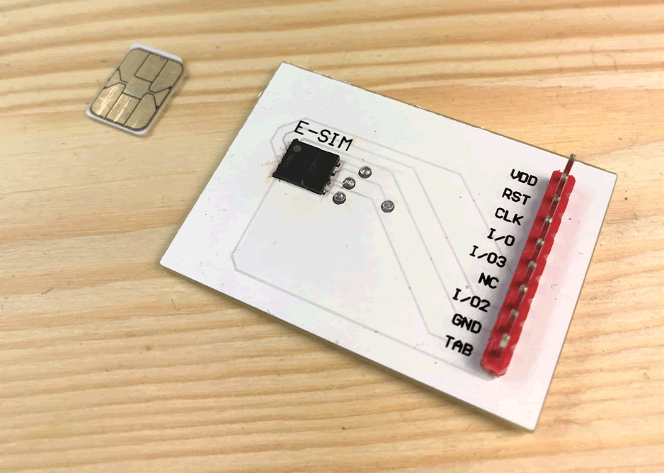
Nano SIM size in relation to an eSIM (attached to a custom breakout board).
Since there’s not that much information out there for hardware-hackers on eSIMs, there’s not much I could find about whether these new eSIMs were pin-for-pin compatible with “normal” SIM cards.
Turns out, they are.
So, with that in mind, here’s a quick rundown on how to make your eSIM device run a normal SIM card:
1. Remove the eSIM
Just like any SMD chip removal, start by applying some (good quality) flux around the eSIM. Get your hot air rework station (or cheap heat gun), apply heat slowly until you can push the eSIM around. Then, you can carefully remove it.
2. Clean the pads.
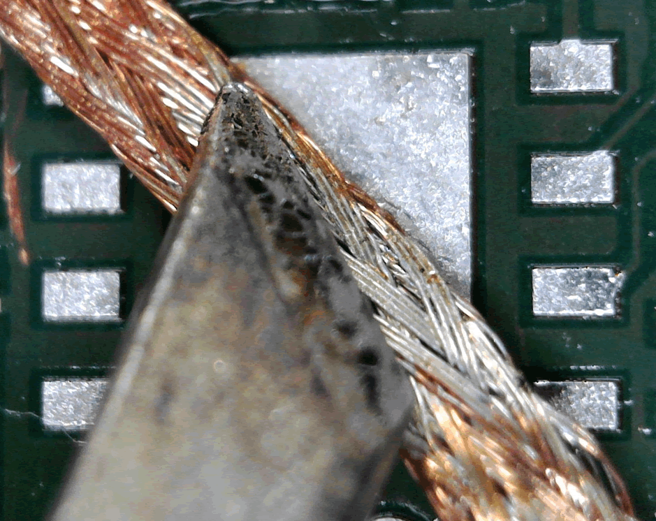
Apply a bit more flux to the exposed pads on the PCB. Use a soldering iron to ball up excess solder. Good flux should help with this – if you’re lucky, it’ll stick to your iron and you can wipe it off on your cleaning wire.
Once you’ve taken off as much solder as you can with the iron, use a small piece of solder wick to “mop” up any excess.
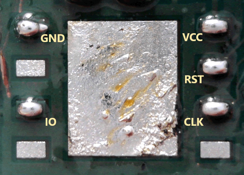
Clean up any excess flux with some isopropanol. You should be left with some nice, flat, clean pads. It might look something like this:
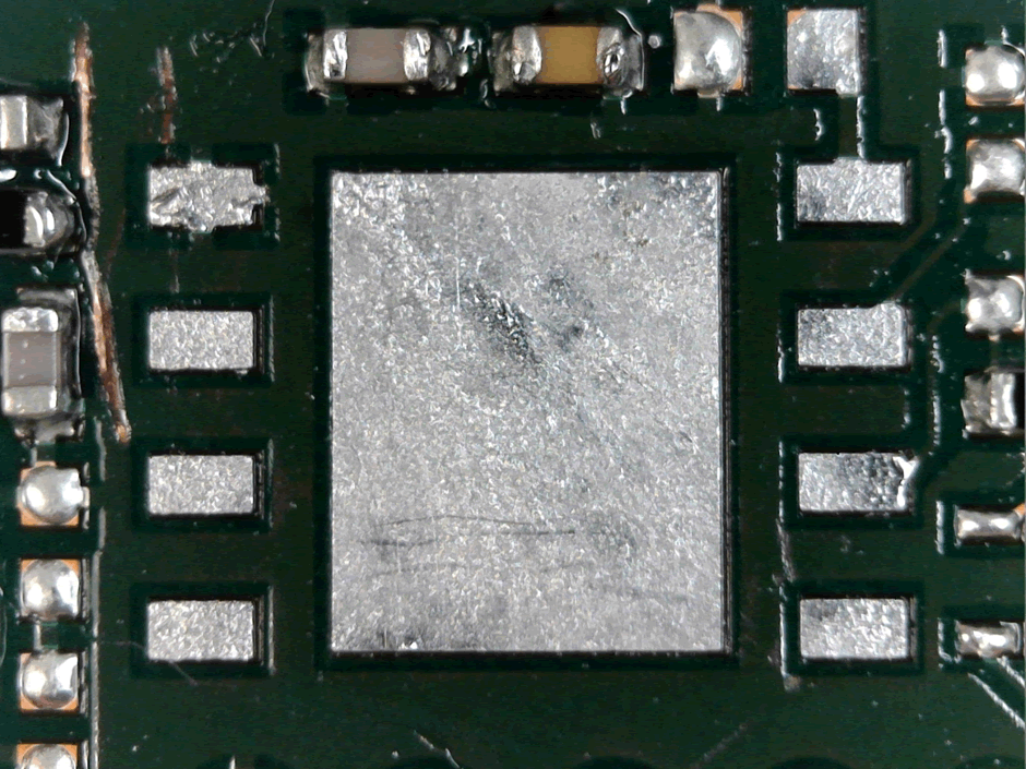
(Although hopefully without scratching off any solder mask!)
3. Tack to the pads
Now we can tack our wires to each of the pads. With MFF2 eSIMs, we only need to tack to 5 pads. The useful pins for us are 1, 3, 6, 7 and 8 – each pin function is as follows:
| Pin | Function |
| 1 | GND |
| 3 | IO |
| 6 | CLK |
| 7 | RST |
| 8 | VCC |
Apply lots of flux. It makes it so much easier to apply an initial solder tack. Each pad is around 0.4 x 0.6mm – so you need a fine iron tip. I personally use a chisel tip, and it seems to work fine.
Apply a little solder to the tip of your iron, hold the tip to the pad just lock enough for the solder to stick, and bring the tip up and away from the pad. This should leave a little blob of solder.
Grab some wire – I tend to use AWG 30 insulated coloured wire. Strip a tiny bit off each end, and tack it to each pin.
You might want to hot-glue the cables to somewhere else on the PCB to take the strain off the solder tacks.
4. Connect to the normal SIM
Now, connect those pads out to your own SIM card – however you choose to do that. You might use a custom breakout board, a broken-out smartcard reader, or even tack directly to a SIM card itself (not really recommended for longevity!).
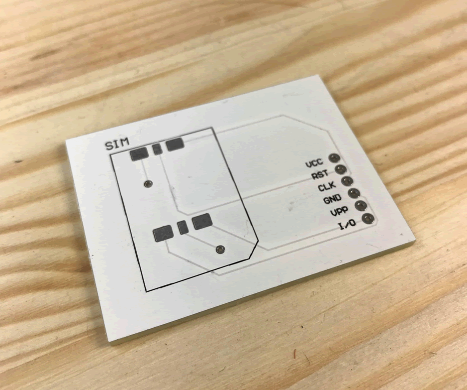
A bare custom SIM card breakout board (no caddy attached).
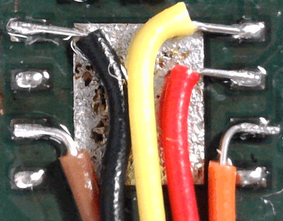
The wires tacked on.
Conclusion
eSIMs vary only by form-factor from traditional SIM cards. While it’s a little trickier to replace them, almost anyone with a soldering iron, a heat gun and a steady hand can do it.
Using an eSIM isn’t a security mechanism in and of itself. It’s a good way of ensuring that it takes a little longer for someone to swap out the SIM in the lab – but it’s worth remembering it’s not impossible.