TL:DR Taking three hardware password managers I used them to:
- Learn the basics of hardware hacking
- Practice disassembling
- Perform chipset research
- Understand pinouts and protocols
- Read data off each device
The passwordFast device uses different ways to store the data on a flash chip with a different architecture. Ultimately the results were similar to part 1 of this series with data being read off the chip, however this time with superior security standards.
Introduction
The first blog of this series looked at the RecZone password vault, the blog went through the steps of a hardware test and explained how to extract data from an SPI chip, resulting the discovery that the data was stored in plain text.
This raised questions including “is all hardware that does similar jobs made in a consistent manner” and “what can be done to improve the overall security of devices like these”?
In this blog I will look at the PasswordFast device working through the same steps to help embed the methodology and looking at any differences between the devices.
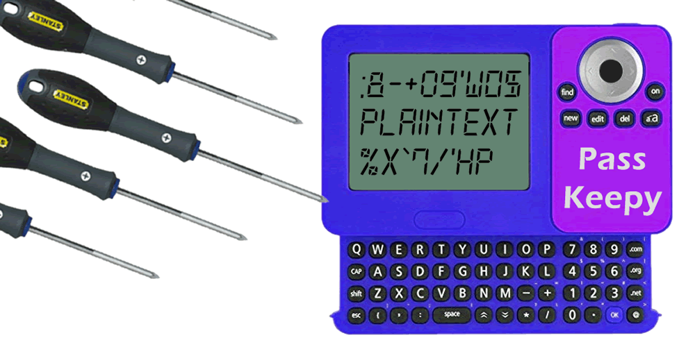
The PasswordFast device’s packaging claims that all passwords are stored in AES256 encryption, if this claim is true this device will be much more secure than the previous device.
Device Set Up
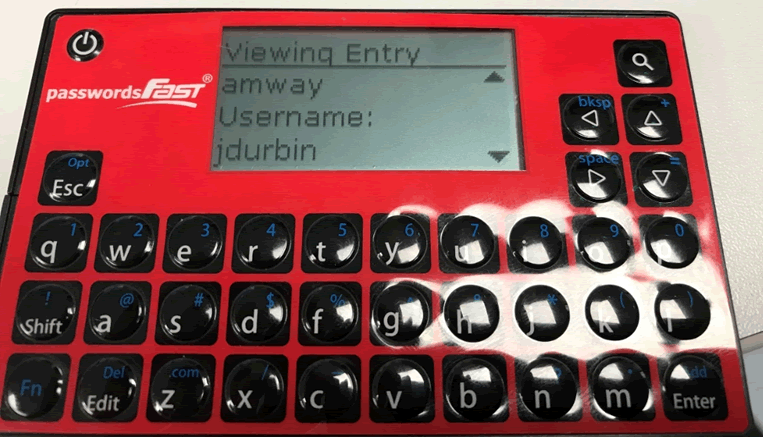
The first step as always is to add example data onto the device. Adding in URLs, usernames, passwords and trying to add in all characters and repeating characters to ease with spotting patterns later on.
Next step is to take the device apart, this was straightforward with this device as the front is sticky plastic which peeled right off.
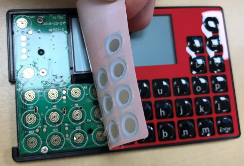
The board underneath was held down by 6 screws, unscrewing these I was able to extract the board from the device.
Initial Inspection
An initial inspection of the board is always the next step, identifying chips and connections.
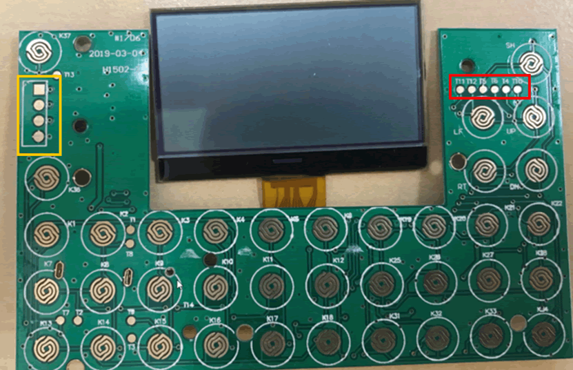
The front of the board has similar keyboard connections however there are two sets of connections in the yellow and red boxes, these may be debug ports. The yellow box looks like UART whilst the red box looks like JTAG connections.
Ideally when secure hardware devices any debug ports should be disabled once all testing has been completed, however this is often not the case.
The back of the board contains a few more components:
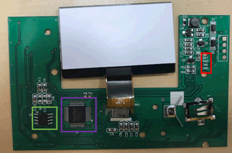
The first thing is the board is what is known as silkscreened, this means human readable information has been printed onto the board. This can be seen on the top right with descriptions for the connections that were seen on the front of the board. The text shows what each connection is (battery, receive data, transmit data and ground) and aligns with the UART standards.
The back also contains two chips, the one in the green box looks to be a flash chip, similar to what was on the RecZone. The purple box looks to be the microcontroller (MCU), the brains behind the board. Unlike last time when it was a blob on board, this chip is exposed so may allow dumping of the firmware to fully understand how the device works.
Chipsets
The MCU is a Nuvoton N78E366 which was found out by reading the text on the chip.
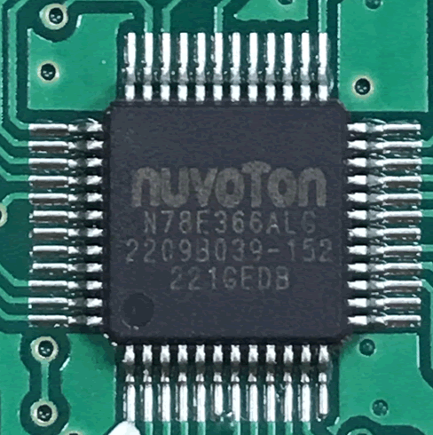
To find out more information about this device, I searched for the specific chip and found the datasheet. The chip is a 8051 compatible chip which is not a standard protocol that’s often found. This means that specific Nuvoton debugger and accompanying software are needed to read the firmware from the chip.
The datasheet also had two other very interesting bits of the information, the chip doesn’t support JTAG, so the connections that were seen on the front of the board aren’t JTAG. Instead I assume these are testing pads to check the keyboard is properly connected.
The second interesting part is that the chip does not have a built in AES encryption module. This means that either they have written their own module and built it into the firmware, or the data isn’t encrypted.
The second chip on the board is the flash memory.
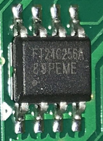
This is the same form factor as the chip found on the RecZone, however the number in the product code is 24, whereas the SPI code seen on the previous chip was 25. Finding the datasheet this is confirmed that this flash chip is using the i2c protocol.
These protocols have a number of differences on how they work at a low level, however the important thing for this project is how to the data is read off the chip.
Dumping the data
As the MCU needs a specific debugger and software which are not easily accessible I decided to park this and instead I focused on the flash chip. The first step was to find the pinout diagram in the datasheet:
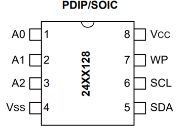
The Vss and Vxx naming is consistent with the previous device. The different pins are the SCL which is clock and SDA which is data.
I didn’t know what pins A0 to A2 were, so I did a continuity test using the multimeter and found that they were connected to ground via the underlying circuit board. As these pins are connected to the ground and I was going to ground the board via the Vss these could be left unconnected. The chip again has a Vcc pin which allowed me to power the chip via the Pi, I2C allows for multi-master unlike the SPIs master-slave mechanism, allowing the Pi and the MCU to access the chip.
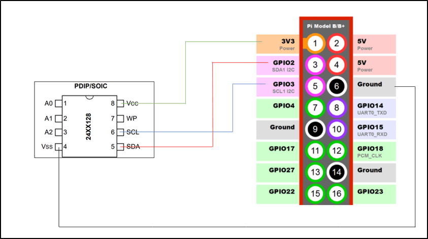
The raspberry Pi has a set of pins for the i2c protocol, similar to with the SPI that was previously used.
The pinouts for the Pi are:

Connecting this device only requires four connections, Vcc for power, Vss for ground, SCL and SDA. Connecting these up looks like:
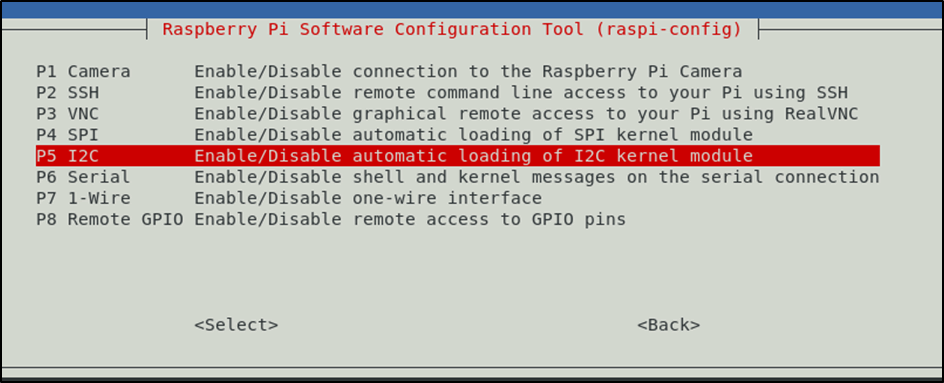
Once connected up the i2c protocol needs to be enabled on the Pi.
sudo raspi-config
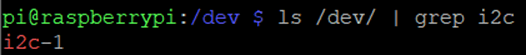
Once the protocol is enabled the location of the connection within /dev/ needs to be found
ls /dev/ | grep i2c
The Pi has a nice feature for i2c which is called i2c-detect. This confirms that the chip has been connected up properly. I needed to pass the command the i2c location, which in this case was i2c-1.
i2cdetect -y 1
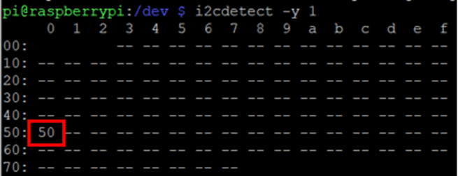
This shows the location of the i2c chip. If the chip isn’t connected up properly, the entire grid will be double dashes.
Unlike the SPI protocol, flashrom doesn’t support i2c and there aren’t many programs that do. However my colleague @tautology0 had previously written a short python script to dump the data. This can be found on his github.
To use the script, it needs run with the output directed into a file.
./i2cutils.py > passwordfast-device2-jd.txt
This will do all the calculations needed based on the chip size and dump all the data into the file provided.
Reading the data
The dumped data is in readable format and can be read with any text editor:
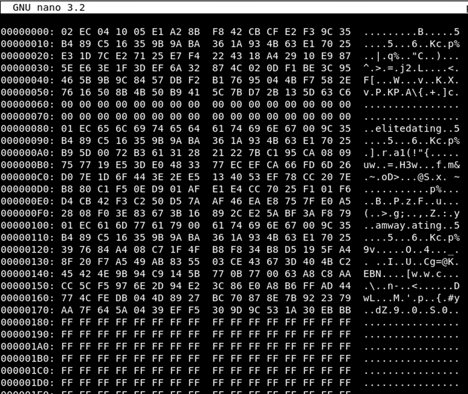
Immediately it can be noted that the data is as advertised, it is encrypted at rest. The two URLs can be seen in plain text, but the usernames and passwords are all fully encrypted.
This shows much better security than the previous device, it did make me wonder if it would be a static key across all device, or different. Luckily, I had a second device, inputting all the same data and dumping the data resulted in different encrypted text. This means that the encryption key is different per device, which is very impressive and exactly what it should be.
There are two avenues that could be taken to try and read the data, the first is to dump the firmware of the MCU and try to work out how the data is being processed. However due to needing the specific debugger and software which wasn’t easily found online, this could be a difficult task.
The other option is to try and do cryptoanalysis on the encrypted data, however this would be ineffective as the encryption keys are different on each device.
Conclusion
There are some similarities between the two devices so far, they both use flash to store the data which means that the data can be read from both of them with basic cheap equipment.
Part three of this series will look at a device that completely bucks this trend and isn’t as accessible with the basic equipment.
For reference here are the links to all three hacking hardware password manager posts:
https://www.pentestpartners.com/security-blog/hacking-hardware-password-managers-the-reczone/
https://www.pentestpartners.com/security-blog/hacking-hardware-password-managers-passwordsfast/
https://www.pentestpartners.com/security-blog/hacking-hardware-password-managers-royal-vault-password-keeper/