
In line with our previous work on the Tapplock, I decided to have some fun with some electronic locks and ordered a few from a large retail company. Half of these are currently en route to me, on the slowboat from China, but one arrived early.
Before I state, let me just say here that I’m not opposed to a fingerprint padlock, in fact I think it’s an awesome idea. It’s just I want one that’s secure and works. Also I enjoy taking things apart…
It was one of these:

It is designed to only be unlocked by fingerprints. The only problem is that it didn’t like either of the fingerprints that I gave it. I would say it would unlock only on two out of every ten attempts that I made on it.
That’s not very good, so I set out to break into it.
Electronic locks can work in a couple of ways:
- Using a motor to turn a spindle to release/lock the shackle (the “loop” that is put through stuff)
- Using a solenoid to move a physical bolt
If badly designed, the first way tends to be vulnerable to brute force, the second to using a strong magnet.
At this point I got a bit carried away and used both a magnet and a bit of jiggling (okay, tugging). It not only popped open, but something must have seized internally as the whole device stopped working. A disingenuous statement could be made here that it was easier to open the lock with a bit of jiggling and a strong magnet than it was to use the “proper” way of opening it.
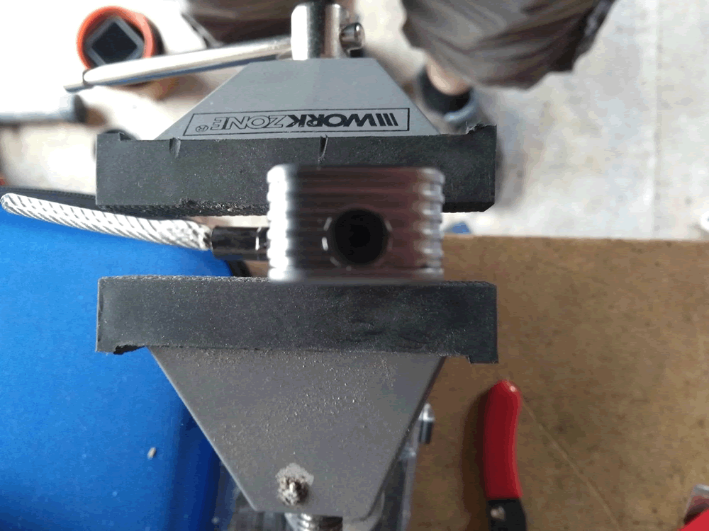
Now I have a broken lock. What else can I do? The website mentions that it has a “high toughness steel wire”? Oh really? Time to take it down the garage and see how tough this really is.
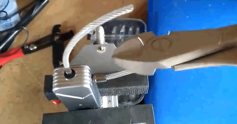
Test number one was a simple pair of snips, designed to cut through steel. These ones cost me about £6 from a regular DIY shop, and they just clipped straight through the shackle.
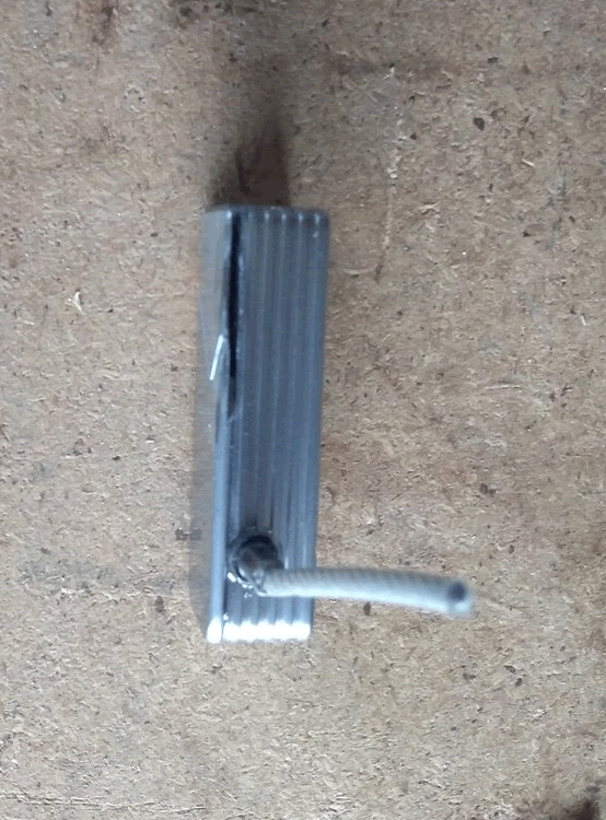
This is well and truly dead now – time to see what’s inside. There’s a thin gap around the non-fingerprint edge, but it’s too narrow to get a spudger in. Time to get out the minisaw and cut it open.
About half way around and I got the delightful smell of a LiPo battery being breached and the whole thing got very hot.
Nothing else to do, but finish what I started. This took a bit longer than planned as I had to keep stopping to let it cool down. At one point I had smoke and flames!
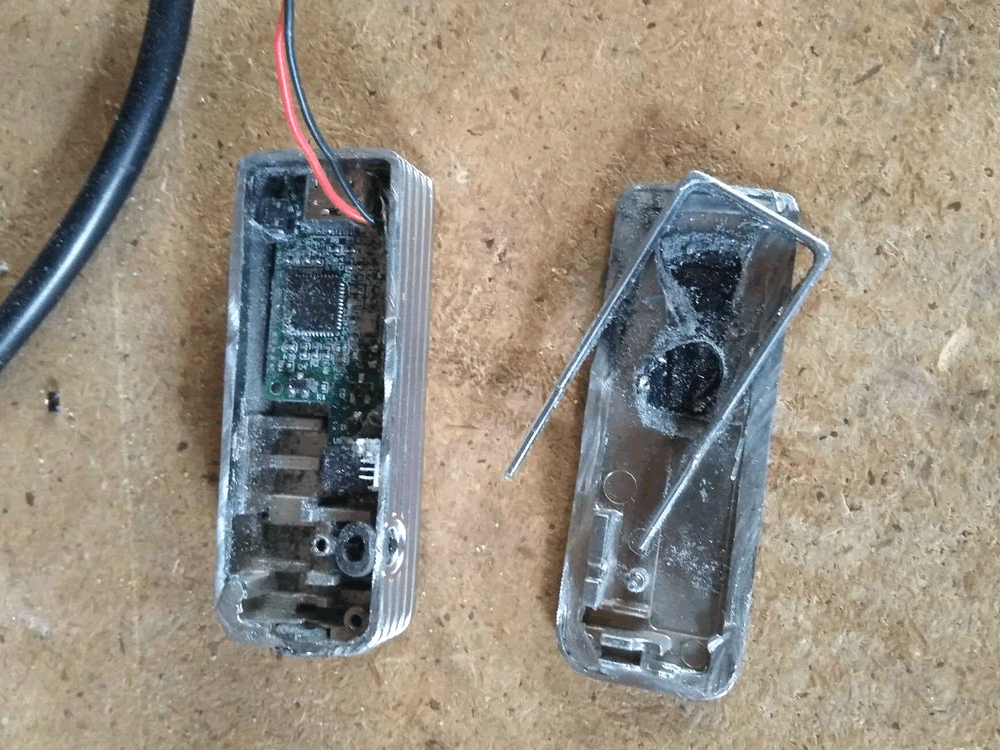
Eventually I cut all the way around and could access the inside. Here’s the inside with a layer of zinc alloy dust covering everything:
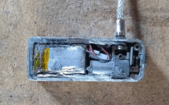
We can see that it uses a motor with a latch, note there’s a tiny circuit board under the latch:
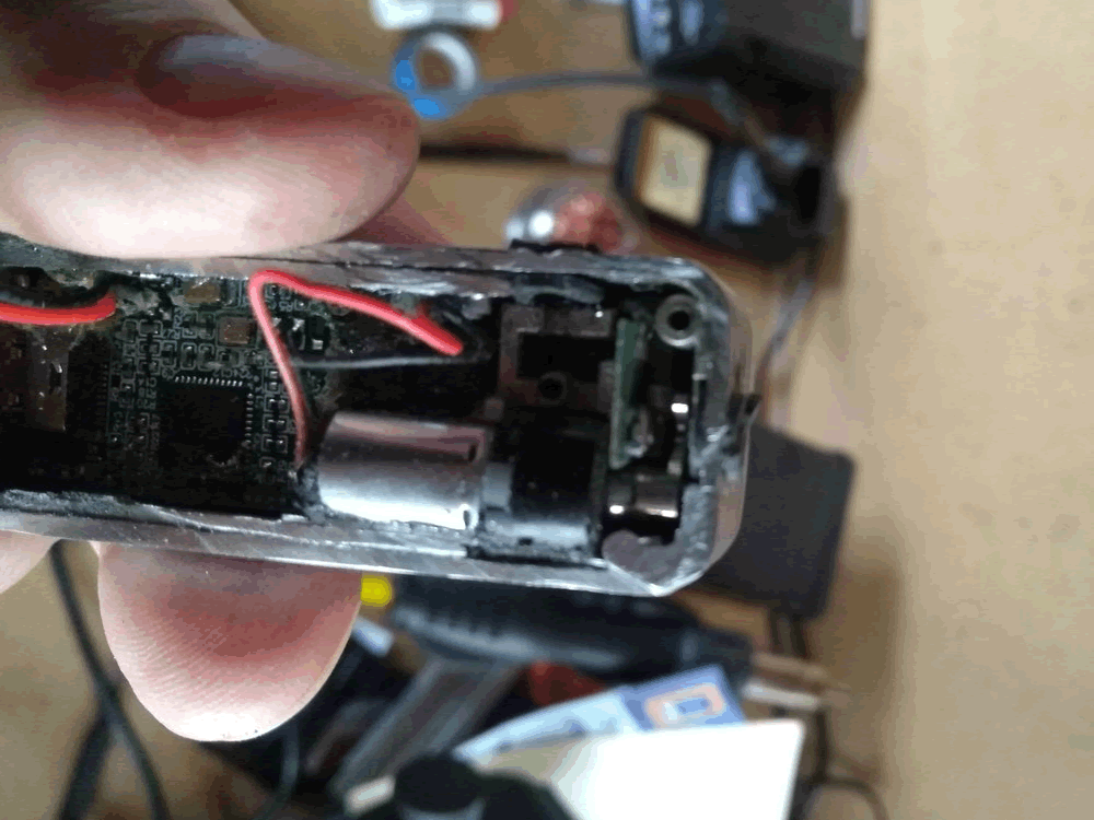
This is just the microswitch that tells the padlock when its closed:
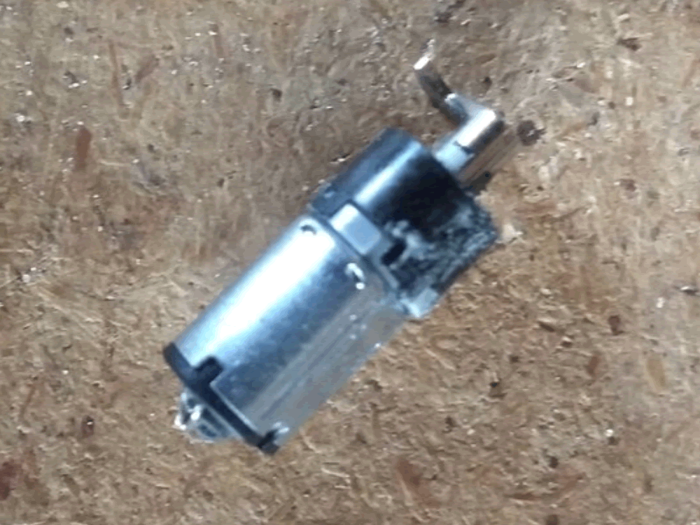
The motor and latch. The motor took a bit of Dremel damage. I think it’s a bit dead:
Now it was apart I could tell that the case scissors together and was probably latched together – this maybe a much cleaner route to get it open if I ever buy another one!
The source of all the flames i.e. where I cut through the cheap LiPo cell:
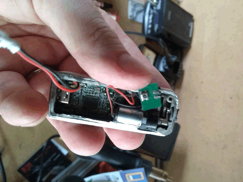
The circuit board – this was all covered in very sticky glue which had been slightly melted when the battery died. I used a pair of tweezers to peel off the glue and some isopropyl alcohol to clean up residue from its extraction.
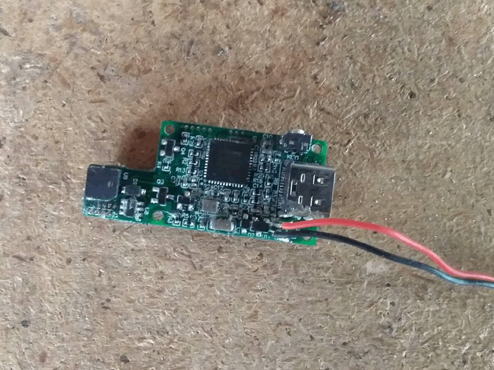
This is the working side. We have an MCU controlling everything with a couple of amplifiers. On the left is the piezo used as a buzzer. The USB C connector is used for powering it. Before anybody asks, I couldn’t get any data on this.
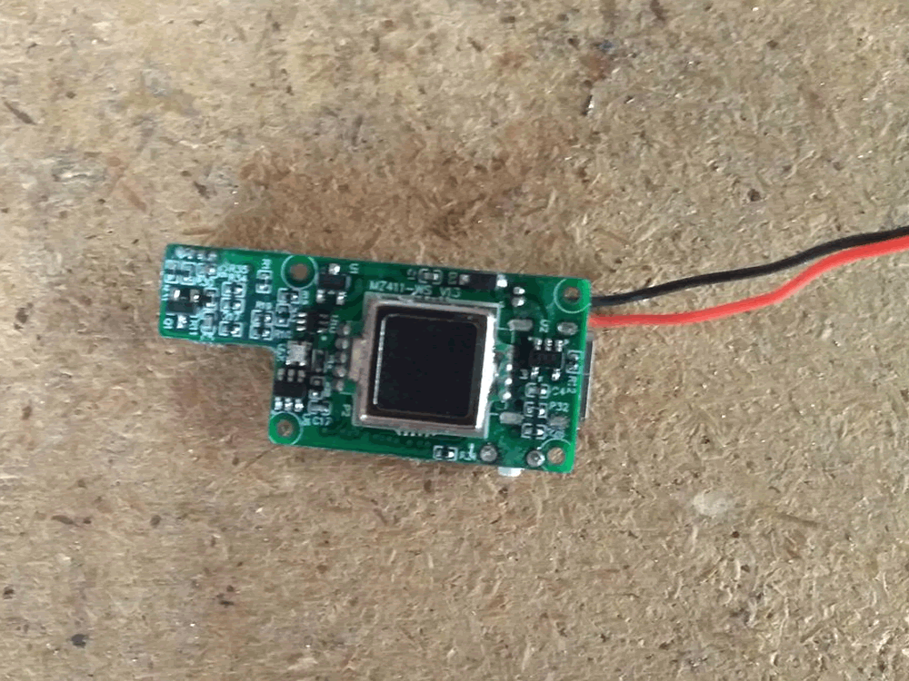
The other side of the board is basically the fingerprint module, which has just been added as a daughterboard:
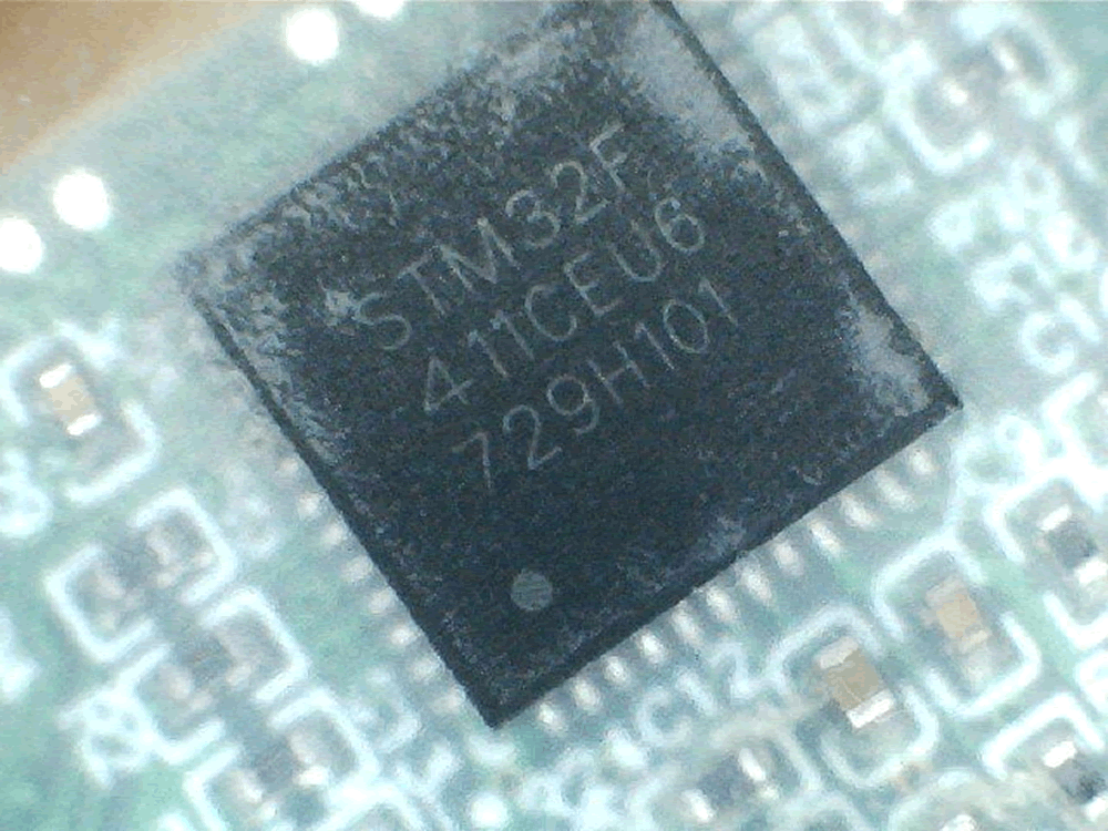
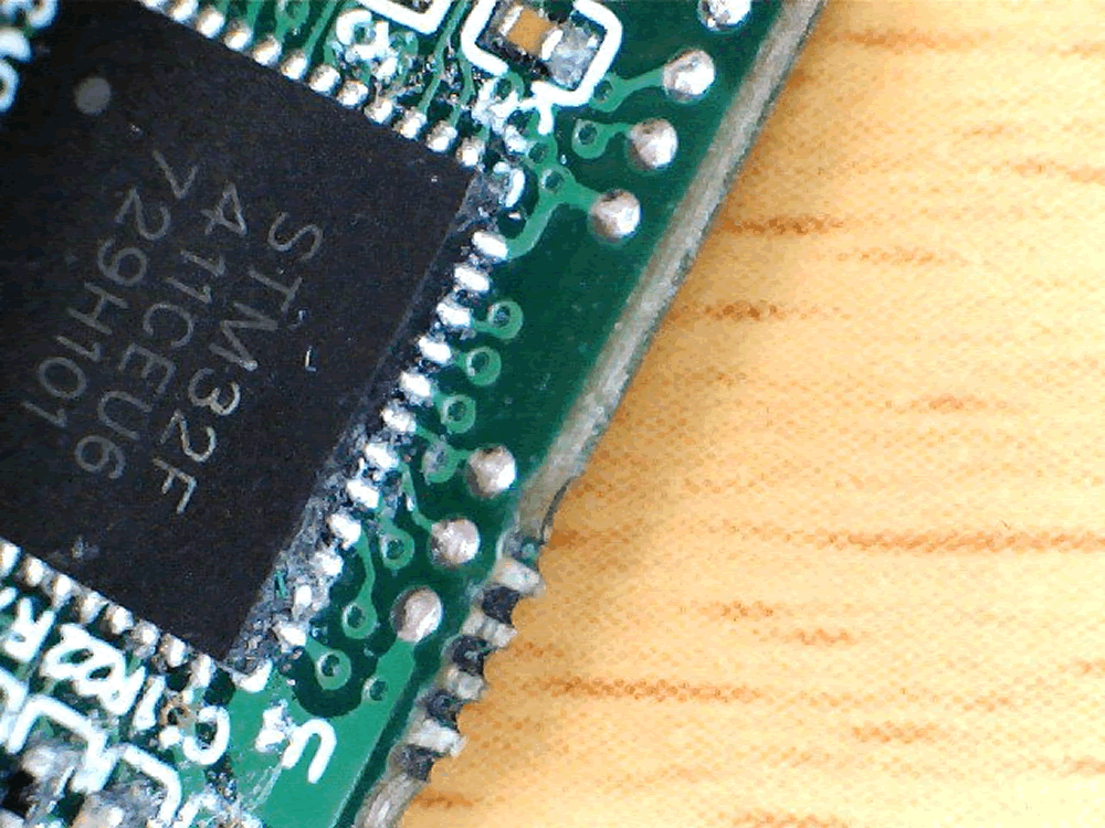
With the board extracted I could have a proper look at the components, the MCU is an STM32F411. This has an ARM Cortex M4 which seems very expensive for what its being used for. I’ve used the Scotch tape trick to make the serial code more readable.
Now if only I knew an STM32 expert… Off to chat to my colleague Chris Wade, our resident, hairy STM32 guru.
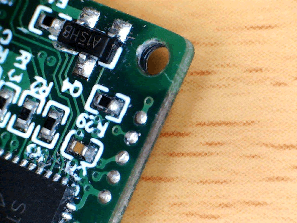
There are two lots of test pads on the circuit board. At the top end is what looks like the SWD interface. The pads buzz out to be:
- Vss
- Not Connected
- SWDCLK
- SWDIO
- Vdd
The Not Connected pad is most likely to be linked to the RESET pin, there’ll just be some components in the way meaning that it won’t buzz out.
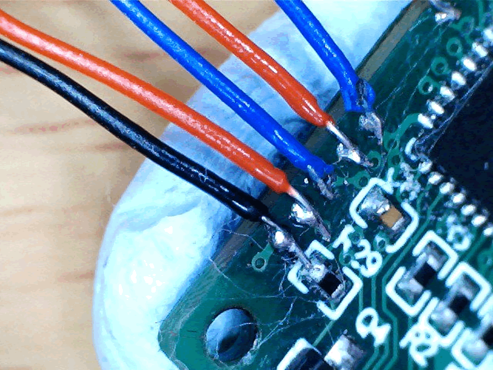
The bottom set of pads. You can see that they are connected to pins PA10, PA9 and Vss. Have a guess what they are… yep, UART!
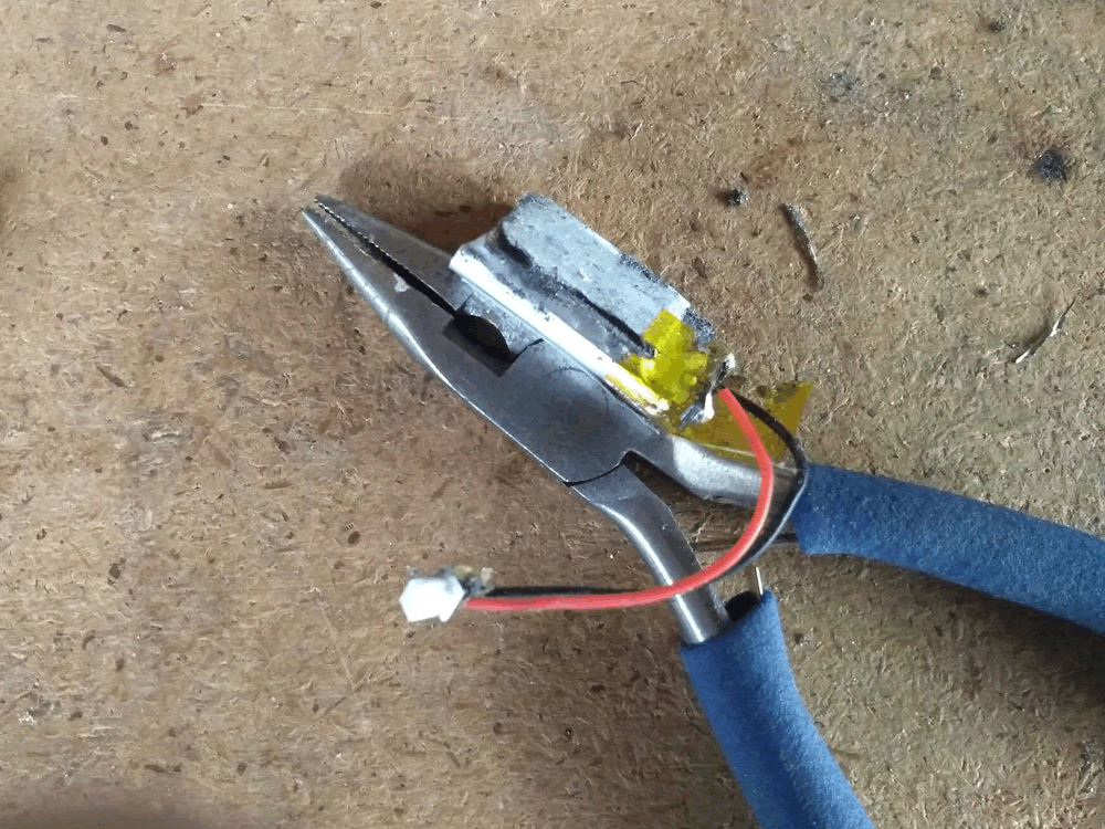
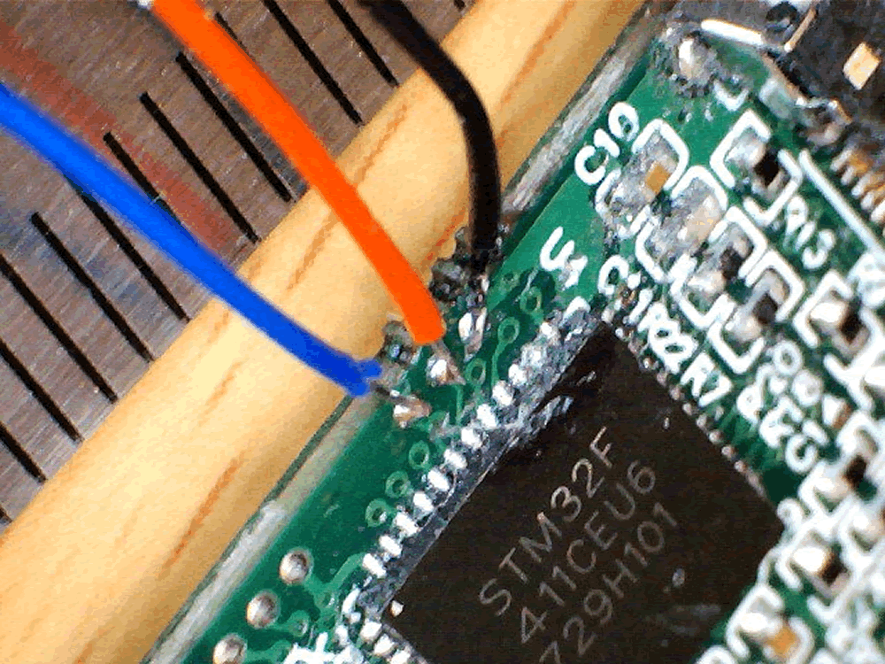
I soldered some AWG30 wire to the UART pads, which was fun as they’re really, really small. I’ve included a rule marked in millimetres for comparison:
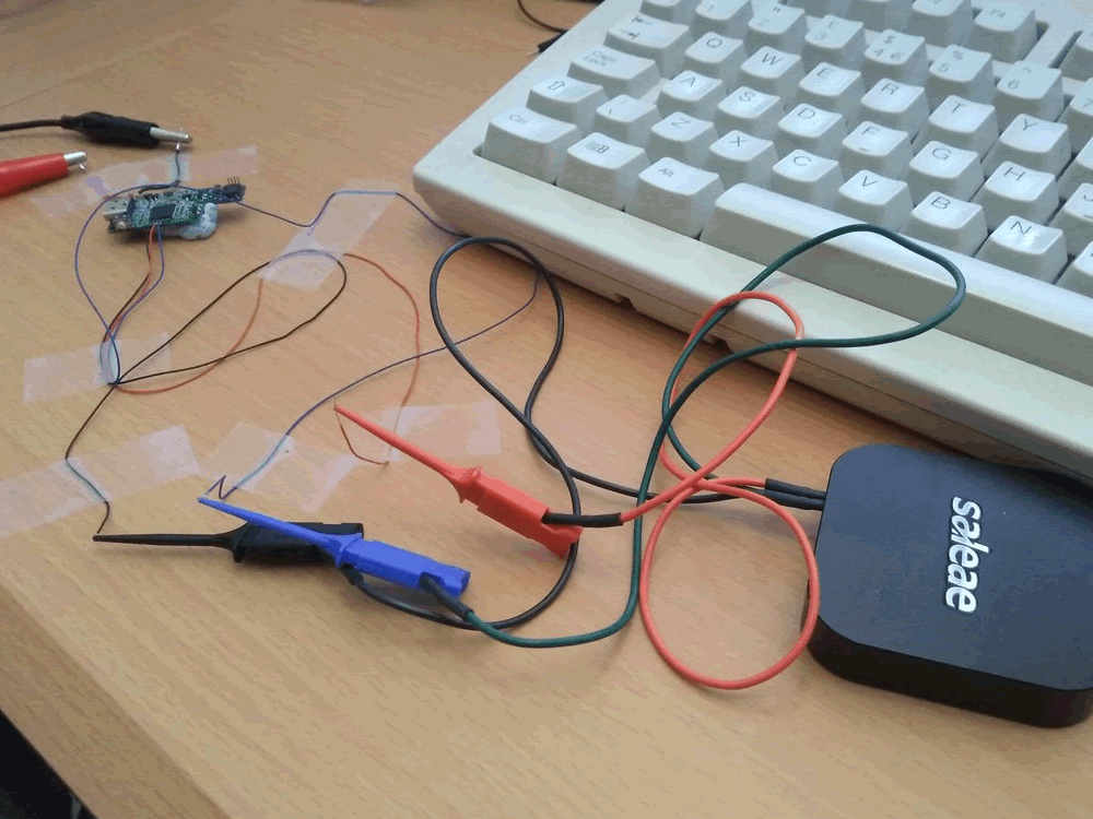
I rigged this up to a bench power supply and connected my Saleae logic analyser. Strangely enough at this point, even with the LiPo fire, it still worked!
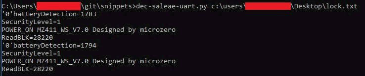
And, yes, we get data on TX when the button is pressed and fingerprint is tried:

Sadly its not useful, the biggest thing we can take is the parameter “SecurityLevel”, but I think this says that I set up an administrator print. We’re also getting a phrase of “Designed by microzero”. This looks to be a reference to the Guangzhou-based Microzero company, makers of a fingerprint identification algorithm system, referenced here.
Finally, I tried to use the SWD pads to get a read out of the MCU’s flash memory:
Connected it to all up to my ST-Link V2 clone and tried it under Linux and got zero flash size, which is a bit weird.

Tried on Windows using the official software. Yeah that explains it: code readout protection.

At this point I’m unlikely to go further, I can already open one of these locks with minimal tools and taking it apart was fun, but without a flash read out I won’t be able to go much further.
Code Readout Protection (CRP) can be bypassed in some cases – my colleague @cybergibbons has blogged about it but this particular MCU doesn’t have a known bypass.